Archive for the ‘engineering’ category

Making the Palm Mini Paddle Stay Put

March 1st, 2016

palm_mini_mount

In my on-going quest to produce a lightweight yet good-performing kit of portable equipment to carry along on my exotic work travels, I set my sights once again upon the Morse keying paddles.  When I was a student, I carried what I had: a black-base Bencher BY-1.  This caught the attention of nearly every airport security screener and was obviously quite heavy, but it stayed put on the table (for the most part) when I aggressively worked a pileup.  A few years back, my wonderful, loving, and patient wife, solicited suggestions for Christmas gifts and I suggested a Palm Radio Mini Paddle.  (She’s grateful when I provide a link to a web site with a shopping cart in these situations.)

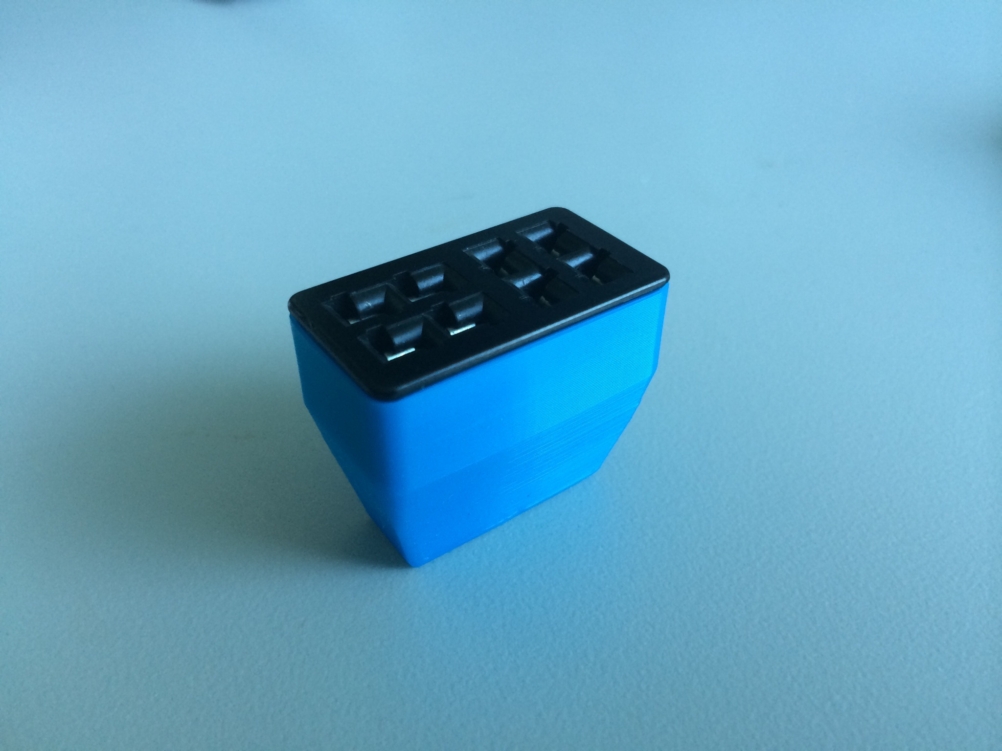
The Palm is really a joy to use and is extraordinarily lightweight, which is perfect for travel.  However, I’ve always struggled with how to keep it steady on a table.  I have the magnetic base, but that presupposes a ferromagnetic surface to which it will mount.  Since both the Elecraft K3 and K2 have aluminum panels, I can’t count on the radio.  I tried a variety of additional things, up to and including, trying to design a 3D-printed carrier that is akin to the Begali Traveler.  So, I shelved the project, only using the Palm key for casual portable operating when mass trumped long-term operating comfort and efficiency.  Good fortune happened upon me and I built this.

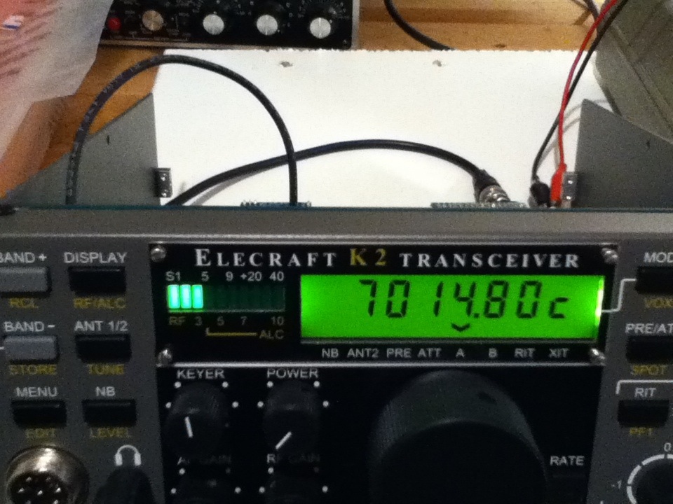
When I decided to add an amplifier (more on this in the future) to my portable setup, again pressure set in on the mass of everything.  So, I revisited the Palm Mini project.  I had purchased a number of mounting clips for the key (hedging my bets against the ephemeral nature of ham radio businesses); so, I set out to attach one to the K2.  I’d seen the photo of the base attached to the right-hand side panel of the K2 by the power switch.  But, I really didn’t want to drill holes in the panel, plus that puts the paddles too high when the tilt bail is raised (which is necessary to see the display).

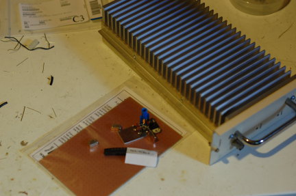
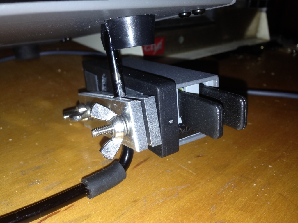
So, I fabricated two strips of 3/16-inch aluminum plate (leftover from the hexagonal beam I built a few years ago) with a hole bored down between them to clamp on the tilt bail of the K2 or the K3.  There’s nothing particularly critical about the construction of it, although I used a Bridgeport mill to do all the cutting; you might be able to do it in a drill press.  I think I ended up with a #14 drill for the clamp hole.  I used 6-32 hardware because I had it on-hand and I like the bigger stuff.  I had to enlarge the adjustment slot in the Palm base to handle the bigger diameter.

50-MHz transverter update (Psst! Newark has cheap 22-MHz crystals)

August 29th, 2015

A few years ago, I built a 50-MHz transverter to operate 6m with my Kenwood TS-930Ses.  I subsequently replaced the two 930s with an Elecraft K3/100 and Elecraft K2/100.  The K3 has 6m and I sold off my TS-700S (and my 6m Mirage brick amplifier) to help finance the internal 2m board for the K3.  The problem with this arrangement is that I can’t be on 6m and 2m at the same time.  I recently assembled and added the SSB board and  transverter interface to my K2 (no time to blog about this but they were straightforward additions like everything from Elecraft), now making it an attractive IF for the 6m transverter (and the Microwave Modules 432 transverter I have on the shelf and the 222-MHz transverter I plan to build sometime).xvtr_50

Enter the problem: Because I was thrifty about building the transverter at first, I had used an inexpensive and widely-available 24-MHz crystal for a 26-MHz IF.  The TS-930S happily worked here (by the way, pro-tip: A lot of guys say that they liked to have the wideband transmit mods on their HF rigs so they could have a wideband signal source for testing/transverters/etc.  The TS-930S will give you a low-level TX out anywhere through the transverter port, even if you don’t have the mod.  Well, at least my PIEXX-equipped 930 did).  However, the K2 only allows a select set of transverter IF bands to be used natively.  Good fortune shone upon my endeavors when I did a quick Google search for 22-MHz crystals and one actually popped up at Newark/Element14 (part number is 86R1720, get ’em while they’re hot)!  Even better news was that it was on closeout for 12 cents apiece!  I splurged and bought five, along with some other parts for another project or two I’ll post about eventually.

I carefully peeled back a layer of dead-bug components, extracted the 24-MHz crystal, and replaced it with the new 22-MHz variety, sacrificing only one 4.7-k resistor, an easily-replaced stock item at K8GU.  The LO came up about 5.4 kHz low and I couldn’t peak it any higher.  So, I’ll either have to futz around with the loading of the crystal or (more likely) load an offset in the K2’s transverter band entry for 6m.

LO_22

The local W3APL beacon popped up at 28.0694 MHz, which is consistent with the offset I observed above.  Now, I just have to get the other interfacing juju worked out to get the K2 to properly command the transverter to transmit and feed it the proper drive level.

Converting the HP ESP120 Power Supply

August 23rd, 2015

Quick notes on converting the HP ES120 2950-watt blade server power supply to run “48-volt” amateur radio amplifiers.  The power supply I have has a slightly different in configuration from the one described by W8ZN on the K8GP site.

hp_001

I picked up the power supply on good terms at Dayton some years ago and finally managed to get around to hooking it up after I put two 240-volt, 20-amp circuits in my shack this spring/summer.  I used a molded air conditioner extension cord with the female end cut off to attach it to the wall.  Hot-ground-hot is the wiring on the AC input side.  On the output, there is a jumper block and two pairs of blade connectors, with one pair being positive and the other negative, strapped together.  In the middle of the output there is a jumper block.

hp_002

Here is where the steps differ from the W8ZN steps:  instead of shorting two pairs of pins together, this power supply requires three in a line to be shorted together.  It’s visible in the photo below, I think.  The center row.

hp_003

I’m getting 51.4 volts unloaded.  Load will be described in the future as it comes to be…

The Pi Day Contrarian

March 13th, 2015

I may be the only person on the Internet who, despite its namesake, finds “Pi Day” on March 14th completely irrational. Here’s why: It’s completely arbitrary. Only we in the U.S. write the date with the month before the day and year like mm/dd/yy. This violates everything sacred about significance in number systems. Normally, digits are ordered from most- to least-significant left to right or least- to most-significance. So, Pi Day including the year actually wouldn’t occur until 3141/59/27 or 31/41/5927, neither of which are real dates anyway. Therefore, Pi Day doesn’t actually exist. I propose a rational alternative definition of Pi Day to be July 22nd (22/7) of every year. Besides, red raspberries are in season in July and not in March so I can enjoy my favorite pie.

Pictures from KH8 (second trip)

March 1st, 2015

I made another trip to American Sa’moa (KH8 for the radio amateurs in the audience) to deploy instrumentation.  It was a tight timeframe but the instruments seem to work and I managed to make a few ham radio contacts as well.

Custom Backshells for Cinch-Jones Connectors

August 7th, 2014

What do you do to complete these hamfest bargains? 3D printing for the win!

IMG_0571.JPG

IMG_0570.JPG
The best thing about it is that you can color-code the connectors, too! Finally, props to a CAD-ninja coworker for whipping up the beautiful SolidWorks model in a couple of minutes.

Latest Tinkering (or how Elecraft is taking all my money)

January 28th, 2014

20140128-055723.jpg

On Christmas Eve, I was sitting at my in-laws’ kitchen table with the Small Wonder Labs SW-40 I built as a high school kid in 1998 listening to beautiful music and I got the itch to come up with a radio smaller (and less expensive) than the K3 to drag around with me when I go places.  My mind wandered to the NorCal Sierra, which was a featured project in ARRL Handbook’s of my youth.  I was able to come up with a draft version of that Handbook article on the web—pause for a moment and think how revolutionary that is—my in-laws don’t have an ARRL Handbook, let alone the one that contained the Sierra article.  I looked at the bill of materials and realized that I had some 70% of the parts in my junkbox.  This seemed like a good idea until I went searching for a PCB.

Why PCB?  Well, I’ve done the dead-bug thing and it works great but it’s a pain to troubleshoot and unless you have decades of experience doing it, it looks like a Mexico City suburb, sprawling unpredictably in every direction with only the most tenuous connections to the core.  Since I was seeking a travel radio, I wanted it to be compact, easy-to-troubleshoot, and relatively rugged.  Due in no small part to the wishes of the Sierra’s designers (not coincidentally founders of Elecraft), boards are no longer available.  I looked into doing my own board, but if you don’t mix chemicals yourself, you’ve suddenly spent $150 on PCBs, plus the layout effort.  I toyed with making the board smaller (a win in several ways) by using surface-mount parts but even that was a non-starter since my junkbox parts are through-hole, requiring me to buy everything.

Astute readers can extrapolate what occurred next.  I went to the Elecraft web site to price the Sierra’s successor, the K1.  I had all but made up my mind to sell off some junkbox items and raise the capital to buy a K1 kit when something occurred to me:  fellow ham blogger Mike, VE3WDM, had recently moved to a smaller QTH and was offering a half-completed K2 kit for sale.  His asking price was only a little more than the K1 kit with some of the options I wanted and it was all-band.   The ad had been posted for some days by this point, so I fired off a sheepish e-mail to Mike asking if the radio was still available.  It was.  We sealed the deal and the radio made the somewhat tortuous ride (for us, not the radio—it sat in Chicago for two weeks) from his QTH to mine via the postal system.

I would not have bought a partially-finished kit from just anyone.  However, since this was Mike’s second K2 build and he was documenting it carefully in a blog, I figured it was a pretty safe bet.  So far, that is definitely true.

While I was eagerly awaiting the radio’s arrival, I redoubled my efforts to get a friend’s TS-930S off of my workbench, a task that involved replacing all 115 electrolytic capacitors on the cookie-sheet-sized “Signal Unit” board (similar to the K2 and K3 “RF unit”).  That radio still has low drive (it has ALC again and sounds like a million bucks), something I traced to a hard-to-find semiconductor that’s now on-order.  So, I gathered it up and started work on the K2 on Sunday afternoon.

Last night, I got it on 40 meters RX-only and peaked up the RX BPF.  Former K2 owner KL9A mentioned to me that it has some blow-by on strong signals but that he thinks it’s a pretty good radio.  I can confirm that based on my experience last night.  It sounds really really good on CW.

More on the build to come…including a look back at some troubleshooting of the BFO circuit.

A Summer Trip to Greenland

August 3rd, 2013

the_office

A professional colleague who is the principal investigator of the Sondrestrom incoherent scatter radar facility announced at a conference that they no longer had a scientific high-rate GPS receiver at the site for making ionospheric measurements.  I enthusiastically volunteered to ship them one that I had on the shelf.  She suggested that instead I should come install it myself and I found some support to do it (the National Science Foundation heavily subsidizes U.S. Greenland and Antarctic scientific travel during their respective summers, making this trip possible).  Therefore unlike my previous trip in the winter, this trip did not involve travel with the most perverse of arrangements flying to Copenhagen only to hop on another plane and fly half-way back to the States.  I set off for my second trip to Greenland, leaving Scotia, NY, early on Monday and returning mid-day on Friday.

On the past trip, conditions were really awful for radio with plenty of visible Aurora.  I didn’t really mind that because the auroras were beautiful, but with only a small chance of NLC/PMC (noctilucent/polar mesospheric cloud) sighting in the summer, I was eager for some good radio conditions to sate my appetite for other nerdy activities.  I set up the radio equipment almost right away the first evening to make sure that everything tuned up and immediately made 10 or so QSOs on 20-meter CW before heading to bed.

Instrument installation is always a hairy business, especially when you can’t just run to a hardware store, let alone going to RadioShack or calling McMaster-Carr.  Sometimes, everything works smoothly; other times it doesn’t.  In any case a flexible attitude (and some good old ham practicality) goes a long way.  Wind gusts of 40-50 mph (18-22 m/s) on top of the hill made for exciting work, but having a couple of helpers made it go smoothly.  Here is a photograph of the installed instrument on its hilltop (the box and green antenna on the right-hand side of the pole, which also held a weather station).

instrument
Work, especially some recalcitrant Windows 7 issues (At one point, I was running Windows 7 in a VirtualBox virtual machine on a Linux machine and logging into the Linux machine from a Mac!), kept me pretty busy on Tuesday and Wednesday and I only managed a few minutes of operating on each of those days.  But, by Thursday, my schedule broke loose a little and I was able to operate for a few solid hours in the afternoon and evening.  I had no idea that Greenland would be so popular on 30 meters!  Wow.  That’s definitely the most intense pileup I’ve ever experienced.  Thanks for being patient.

There was some about S3 hash on 20 and 30 meters that the K3’s NR function would take care of but the NB function wouldn’t.  NR is not good for running pileups, so I often had to get the caller isolated to use NR.  On the receiving end, there was a lot of fast QSB, with a period of a few seconds (this is consistent with magnetospheric and plasmaspheric waves that impinge upon the auroral and subauroral regions.)  In any case, callers were up and down, often in the span of a call.  You all on the other end may or may not have observed the same from me.

Per usual, the setup was an Elecraft K3 and the GU Special vertical with 2x 1/4-wavelength radials for each of 20 and 15 meters.  Everything else was tuned by adjusting the length of the radiating section.  This is a substantial improvement in performance-to-size ratio over the previous station I carried in January 2012, which was a Yaesu FT-840, DK9SQ 10-meter telescoping pole, and a variety of wire antennas.  Below is a photograph of the GU Special deployed (it’s in the center, unceremoniously ty-wrapped to a wooden sign post sticking out of a barrel).  The diesel Toyota HiLux pickups are the most popular vehicle in town.  We gave a visiting graduate student lessons in driving a manual transmission.  Great vehicle to teach/learn on with lots of torque and low gearing!

gu_special_sonde

Although I was unable to connect with them, we did drive past the OX2A/XP1AB site on Black Ridge that overlooks downtown Kangerlussuaq:

ox2a_xp1ab
Thanks for the QSOs.  The log has been uploaded to LoTW this morning and QSL cards are ordered.  I never ordered cards after the last trip, so it will be a shared card with a photograph of the aurora.

Review: Array of Light (3rd Edition)

July 9th, 2013

My friend Matt, KB9UWU, eggs me on to buy things.  Sometimes I listen.  Sometimes I don’t.  But, eventually he wins me over and I’m usually happy with the purchase (e.g., K3 and Hex beam, although I built the Hex from scratch, which reminds me that I owe the blog a discussion of that).  I like to think that I let Matt be the early adopter and then pick and choose based on his experience.  He convinced me to buy a copy of N6BT’s book Array of Light.  Here’s my review.

If there’s anybody that knows antennas in the amateur community, it’s Tom Schiller, N6BT, the founder of Force12 and now owner of N6BT Next Generation Antennas.  He’s also a member of the very successful Team Vertical contest team, who have revolutionized DXpedition and contest expedition antenna systems by replacing trapped tri-band Yagis like the TH-3jr(s), TA-33jr, and A3S, with arrays of verticals located at the water line.  Schiller’s work has been nothing short of revolutionary so I had high hopes for the book.

My copy, like every other copy, is signed by the author.  It’s a good-quality laser print and has the same spiral binding as the Elecraft manuals.  The book is a loosely-edited collection of articles and clippings that read pretty well in series.  But, it’s bear to skim or go back to find specific things unless you’ve read the whole thing cover-to-cover a couple of times.  But, that’s pretty easy to do because Tom is a good storyteller.  My only other complaint is that there are a couple of places where I think Tom has drunk his own Kool-Aid regarding the efficiency of his antennas, especially “linear loading.”  This is a topic that I need to revisit with a pencil and paper study at some point because there is a lot of misinformation floating around about traps, linear loading, and “multi-monoband” antennas.  It’s not clear to me that anyone has sat down and really examined this in a methodical way.  It was disappointing that he quoted numbers like “greater than 99% efficiency” without going into more detail about the efficiency of a full-size antenna versus the linear-loaded one, etc.  Of course, this is difficult, but it’s something that always makes me a bit skeptical.

Array of Light is worth the price of admission for a couple of reasons—the first is the stories and the second is the antenna designs.  I’m a big proponent of not reinventing the wheel on most of my homebrew projects and this book is sure to provide some proven designs to work with.  Especially if you want a good discussion of practical antennas for DXpeditioning and contesting I think it’s a real winner.

Do you see what I see?

July 7th, 2013

222_start

  1. Crystal oscillator for 98.5 MHz.  Check.
  2. TUF-1 and TUF-3 mixers.  Check.
  3. SMT protoboard.  Check.
  4. MMIC amplifiers.  Check.
  5. Larcan TV exciter amp.  Check.

Do you see what I see?  Yes, a 222-MHz transverter is on the horizon.