Posts Tagged ‘ts930’

Latest Tinkering (or how Elecraft is taking all my money)

January 28th, 2014

20140128-055723.jpg

On Christmas Eve, I was sitting at my in-laws’ kitchen table with the Small Wonder Labs SW-40 I built as a high school kid in 1998 listening to beautiful music and I got the itch to come up with a radio smaller (and less expensive) than the K3 to drag around with me when I go places.  My mind wandered to the NorCal Sierra, which was a featured project in ARRL Handbook’s of my youth.  I was able to come up with a draft version of that Handbook article on the web—pause for a moment and think how revolutionary that is—my in-laws don’t have an ARRL Handbook, let alone the one that contained the Sierra article.  I looked at the bill of materials and realized that I had some 70% of the parts in my junkbox.  This seemed like a good idea until I went searching for a PCB.

Why PCB?  Well, I’ve done the dead-bug thing and it works great but it’s a pain to troubleshoot and unless you have decades of experience doing it, it looks like a Mexico City suburb, sprawling unpredictably in every direction with only the most tenuous connections to the core.  Since I was seeking a travel radio, I wanted it to be compact, easy-to-troubleshoot, and relatively rugged.  Due in no small part to the wishes of the Sierra’s designers (not coincidentally founders of Elecraft), boards are no longer available.  I looked into doing my own board, but if you don’t mix chemicals yourself, you’ve suddenly spent $150 on PCBs, plus the layout effort.  I toyed with making the board smaller (a win in several ways) by using surface-mount parts but even that was a non-starter since my junkbox parts are through-hole, requiring me to buy everything.

Astute readers can extrapolate what occurred next.  I went to the Elecraft web site to price the Sierra’s successor, the K1.  I had all but made up my mind to sell off some junkbox items and raise the capital to buy a K1 kit when something occurred to me:  fellow ham blogger Mike, VE3WDM, had recently moved to a smaller QTH and was offering a half-completed K2 kit for sale.  His asking price was only a little more than the K1 kit with some of the options I wanted and it was all-band.   The ad had been posted for some days by this point, so I fired off a sheepish e-mail to Mike asking if the radio was still available.  It was.  We sealed the deal and the radio made the somewhat tortuous ride (for us, not the radio—it sat in Chicago for two weeks) from his QTH to mine via the postal system.

I would not have bought a partially-finished kit from just anyone.  However, since this was Mike’s second K2 build and he was documenting it carefully in a blog, I figured it was a pretty safe bet.  So far, that is definitely true.

While I was eagerly awaiting the radio’s arrival, I redoubled my efforts to get a friend’s TS-930S off of my workbench, a task that involved replacing all 115 electrolytic capacitors on the cookie-sheet-sized “Signal Unit” board (similar to the K2 and K3 “RF unit”).  That radio still has low drive (it has ALC again and sounds like a million bucks), something I traced to a hard-to-find semiconductor that’s now on-order.  So, I gathered it up and started work on the K2 on Sunday afternoon.

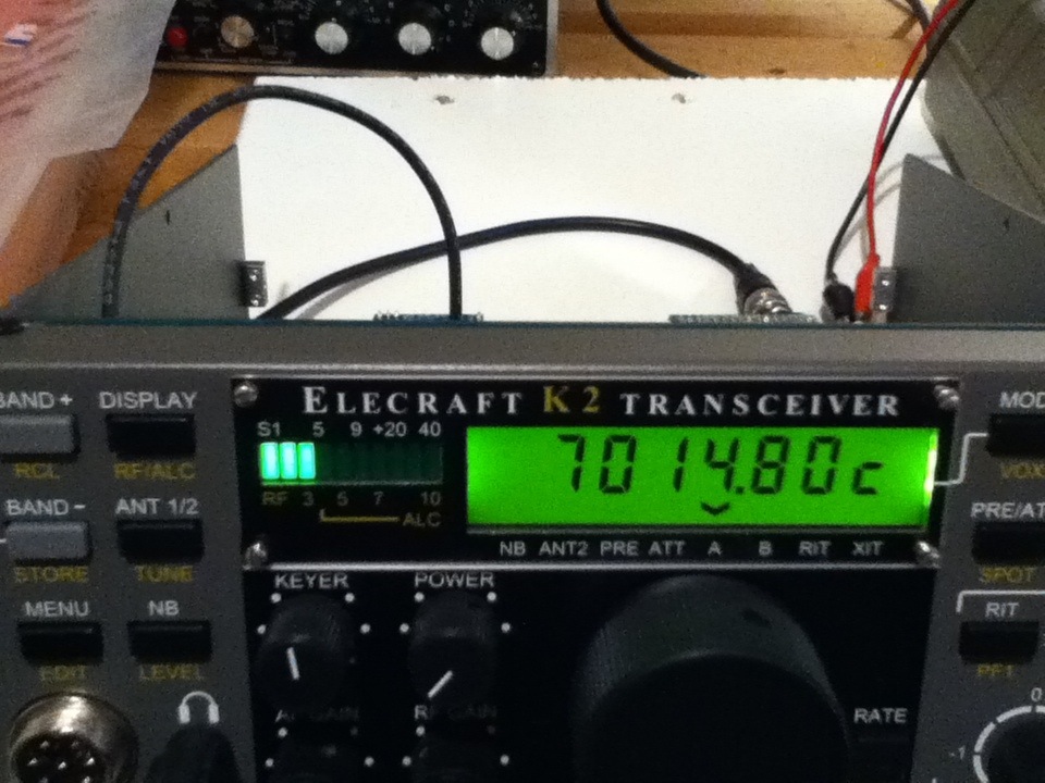
Last night, I got it on 40 meters RX-only and peaked up the RX BPF.  Former K2 owner KL9A mentioned to me that it has some blow-by on strong signals but that he thinks it’s a pretty good radio.  I can confirm that based on my experience last night.  It sounds really really good on CW.

More on the build to come…including a look back at some troubleshooting of the BFO circuit.

RYRYRY O RLY?

February 27th, 2011

A few readers of this blog may have been surprised to contact me on a new mode last night…RTTY.  I’ve tried radioteletype once before in the past (also in the NAQP contest) but rather unsuccessfully the first time.  The second outing was a bit better.  I suppose with practice it becomes fun, but the primary motivation here is ARRL’s Triple Play award for contacting all 50 states each three times, using CW, SSB, and digital.  CW was, of course, easy.  And, I’m making good progress on the SSB totals.  So, I figured I would stop putting RTTY off and give it a shot.

As you are probably well familiar, I normally contest with two TS-930s.  Their prior owners (who were CW contest/DX types like myself) made various “improvements” to them, most of which I appreciate, but I have no idea how they affect FSK. One radio simply does not work on FSK (need to look into this) and the other has the passband shifted about 50-100 Hz off-center of the normal RTTY frequencies. So, when I was running AFC in MMTTY, it would “walk” to the point that having a lock on the other station would put me at the edge of their passband. I had a terrible time making QSOs for the first hour until K0TI told me I was off-frequency (thanks, Dan!!!) and then I started paying attention to all of the numbers in MMTTY and turned off the AFC, which had some deleterious effects that I overcame thanks to the occasional repeat. Typical analog op becomes digital lid op.

I sent the MacBook (our “home” computer) with Sarah to a conference yesterday.  Since that’s the only place I have LoTW’s Trusted QSL installed and I failed to export a .p12 file, I’ll have to hold tight for a couple of days until they return.  (This is not entirely true, I have an old .p12 file, but I haven’t backed it up again since I renewed the certificate a few weeks ago.  Bad backup practices…although I just got a new external drive so the old drive can be used to do a Time Machine back up…finally.  Another day, another project.)

This post mostly mirrors my 3830 post, but here are the numbers for the curious.  My grepping missed one QSO on 80 meters when I did the totals (N1MM rounded the frequency up to 3600 kHz) for 3830.  So, these numbers are right, aside from log-checking discounts:

Call: K8GU
Operator(s): K8GU
Station: K8GU

Class: Single Op LP
QTH: MD
Operating Time (hrs): ~3

Summary:
 Band  QSOs  Mults
-------------------
   80:   37    21
   40:   58    27
   20:   35    18
   15:
   10:
-------------------
Total:  130    66  Total Score = 8,580

Club: Potomac Valley Radio Club

Team: PVRC #1

Recent tinkerings (9 Jan 2011 edition)

January 9th, 2011

Several people have commented over the years that I should “write more” on the blog.  I usually respond that I could spend my free time tinkering/hamming or blogging, but not both.  Here are a month’s worth of blog posts as freestyle poetry:

  • A section on my workshop has been added to k8gu.com under Engineering.
  • Discovered that although the SoftRock VHF Ensemble II won’t fit (barely) into the Bud CU-473 diecast box I bought for it, it will fit into an extruded enclosure that housed an ancient X-band radar detector I picked up at Dayton in 2002 in hopes of stripping the Gunn diode assembly and getting on 10 GHz.  Bonus points for thriftiness.  Photos will follow once I finish the project.
  • Did not observe Quadrantid meteor pings with the SoftRock VHF Ensemble II, but did notice something interesting about the W3APL beacon.  Need to investigate.
  • Have more CE/K8GU QSL cards again, finally.  Tonight, I might finish the bureau (and, ashamedly one direct) cards languishing.  Some K8GU (and AA8UP, no kidding) bureau cards are sitting here staring at me, too.  Not a big project, though.
  • Operated the NAQP CW on Saturday (8 January 2011) for four hours and twenty minutes and made 318 QSOs x 128 multipliers for 40,740 points before log-checking discounts.  This total is pleasing to me especially considering that it was almost all leap-frogging SO2R search-and-pounce, which can be very fatiguing.  It’s fun to see the rate meter stay over 100 when you’re S&Ping.  Good Sprint practice.
  • Still the best 30 minutes on the radio every week:  I operated the NS Ladder on Thursday (6 January) night and made my customary 30 QSOs x 24 multipliers for 720 points.  Hopefully, adding 160 will give me some momentum to increase this score back over 1000.
  • We had a spell of 50F (10C) weather on New Years’ Eve.  So, I put the 2-meter beam back up on the chimney.  It was formerly mounted on a steel mast that was ratchet-strapped to the chimney.  A strong wind (>50 mph gusts) before Christmas bent the mast (actually a fence top-rail) and I had removed it.  I cut the bent lower portion of the mast off and attached the remaining top portion with rotator to a “girder” constructed from two pieces of treated 2″ x 4″ x 10′ lumber joined with a half-dozen lag screws.  Again, I ratchet-strapped the entire assembly to the chimney.  The present configuration is much stronger and less prone to damage.  The 3-element 50-MHz Yagi is still on the ground until I actually get the transverter finished, which should be soon (as it has been for 12 months now).
  • Repaired a SoftRock v6.2 downconverter for WF1L and learned that you can solder leads back onto SOIC packages if you’re careful.
  • Have had delightful exchanges with KN6X and ZL1CDP about repairing the TS-930S.  Some of these discussions (and their fruits) may make it onto the site at some point.
  • Back in December, I started integrating the W1GHZ transverters using UT-141 semirigid jumpers with pre-installed SMA connectors obtained on attractive terms from Max-Gain Systems.  Mitsubishi RA18H1213G (1296 MHz) and RA30H0608M (50 MHz) modules arrived from RF Parts.  May have a lead on something less expensive with more gain for 903 MHz via HA1AG.  The big remaining tasks in all three transverter projects are the sequencer and IF interfacing.
  • Also in December, I had dinner with NS Ladder father Bill, N6ZFO, in San Francisco at the Hyde Street Seafood House & Raw Bar, which is a favorite of NA Sprint father, Rusty, W6OAT.  Yes, I did feel that I was in the presence of greatness.  (I had their excellent pork chops since I’m not into seafood, especially raw seafood.)  Like most contesters, Bill’s a super, fascinating guy apart from his radio contesting interests.

TS-930S PA/PS Postscript

August 11th, 2010

Long-time followers of the blog know that one of my TS-930S transceivers has been a money and time sink for about the past five years, fully 60% of the time I’ve owned it.  So, if you haven’t been following the story over the past couple of months, I pretty much replaced (almost—get to this in a second) all of the electrolytic capacitors in the power supply and power amplifier, plus replaced the driver and final amplifier transistors.  As I increased the drive past the point where I got 50 watts output, I started to get a lot of AC hum on the signal.

At first, I thought the hum might be associated with a low-frequency instability in the power amplifier.  I read all the Helge Granberg articles I could find on the topic and tried all of the prescriptions he suggested.  Last night, I even went so far as to tweak the feedback resistances in the PA stage to increase low-frequency stability.  Still there.  Finally, I measured the frequency of the AC hum—exactly 120 Hz—full-wave bridge rectifier leakage.  Tonight, I pulled the power supply board out of the radio, which is a herculean task, by the way.  There were still three small, insignificant-looking electrolytic capacitors that I hadn’t changed.  I found two of them in my junk box and crossed my fingers on the third one (a 25 uF, 100-volt unit), leaving it in place.  While I had it out, I also found and shunted a pair of dying PCB traces with pieces of wire.

After putting the board back into the radio, I disconnected the PA 28-volt line and powered it up.  I checked the 28B voltage…right on 28.5 volts.  So, I reconnected everything and it fired right up at 100 watts without the hum.  Perseverance seems to have paid off.  For now.  I keep telling myself that the next time it breaks, I’m going to get a K3/100.  But, I just can’t bear to buy a radio that’s worth more than my car.

More on the TS-930S PA

July 29th, 2010

I put the “troublesome” TS-930S back on the bench again yesterday to investigate its PA instability some more.  A few points are worth mentioning:

  1. The instability onset power gets lower with increasing frequency.  That is, at 7 and 14 MHz, the instability onset is at about 60 watts output.  At 28 MHz, that drops to 40 watts.
  2. I was able to increase the onset power slightly by increasing the resting bias of the MRF-422/2SC2510A pair from 1.1 A to 1.5 A.  I don’t know if that was a real effect or just a coincidence, though.
  3. I tried adding 0.001 uF, 0.1 uF, and 4.7 uF capacitors shunting the 28B line to ground to remove RF that I observed on that line during transmit.  I don’t have a good measurement of the amount of RF, yet.  But, I know that it’s the same frequency as the transmitter because it varies as I change bands.

I still need to find that Helge Granberg article from RF Design to locate the references.  Still counting my lucky stars that I haven’t destroyed anything in the course of these experiments.

TS-930S PA mod — first try

May 25th, 2010

As I wrote recently, I have been tackling the low-frequency instability problem in the TS-930S PA unit.  My first attempt was to add several bypass capacitors to from the supply side of L7 to ground (through a lug on the Q7 mounting screw a short distance away).  This should tame the drivers, although the problem is not there.

The hum came back when I pushed the power beyond about 50 watts.  The push-pull MRF-422 final amplifier circuit in the TS-930 comes from Motorola EB27, with a few small modifications.  However, it is not clear to my untrained eye where additional precautions could be taken.  I have a hunch that my next target will be this portion followed by the 2SC2075 pre-driver stage if I come up empty on the finals.

More on the TS-930S PA

May 21st, 2010

I’m not sure that I’ve shared this on the blog, but I’ve long known that the reason that my “troublesome” 930 burns up PA drivers is a low-frequency oscillation.  This mechanism was also mentioned by Leeson in his comprehensive list of 930 upgrades and repairs.  At first, I thought that the 28-volt power supply’s filter capacitors might be the culprit—insufficient ripple-suppression.  After all, the oscillation sounds like it has a 60-Hz component (I’ve never tried to measure this because I’m concerned about blowing up more transistors).  I finally completed the capacitor replacement last night, realigned the power supply voltage and PA bias levels…and the oscillation is still there, just as I increase the drive past the point where I get 50 watts out.

There is a good Helge Granberg article in the September/October 1980 issue of RF Design titled “Good RF Construction Practices and Techniques.”  I would like to get a copy of the original article because Motorola, in their infinite wisdom, reprinted the article as AR164 but neglected to include the list of references.  Granberg devotes an entire section of the article to instabilities, a full of half of that section to low-frequency instabilities.  This is the area I will focus on first:

Causes for the low frequency instability are usually inadequate collector DC feed bypassing or an extremely poor ground in that area.  Two or three RF chokes together with various values of bypass capacitors from 1000 pF to several uF may be required in the DC line to stabilize the circuit.  (See examples in Reference 1.)

Ah, Reference 1, where (who) art thou?

If I ever get to the bottom of this problem, there should be a useful body of work and notes to prevent this from happening repeatedly to others.

TS-930S repair notes (17 April 2010)

April 17th, 2010

This is just a quick note summarizing my repair of the 5-million S/N TS-930S.  Both the fragile MRF-485 drivers and the hardy MRF-422 finals were toast.  The power supply pass transistors (2N5886s) were also dead.  Two electrolytic capacitors in the PA bias network over-voltaged and exploded.  Original cause unknown, but certainly exacerbated by a slipped probe when setting the driver bias previously.

I almost wrote this one off and parted-out the goodies from this radio to finance a new radio.  But, when I saw the price of a used Orion or properly-configured K3/100, I realized I could repair this one a lot of times and save my money for my newly-acquired VHF+ habit and the eventual, mythical, first tower.

To begin with, I got the power supply working again with my last set of spare 2N5886s.  Should buy a half-dozen more of these to keep on-hand.  With the PA disconnected, I set the 28B line at 28.5 volts.

Now for the big job:  I tore-down the entire PA board, cleaned it, and cleaned the heatsink.  Replaced all of the bias resistors with new carbon composition types from Mouser.  Replaced the MC1723 regulator IC in the PA bias with LM723.  Replaced all electrolytic capacitors in PA.  Replaced drivers with MRF-485MP-HB (matched-pair, high-beta) from RF Parts.  Used all-new mounting hardware and mica insulators.  Replaced finals with 2SC2510A-MP, also from RF Parts.  This part is essentially the Toshiba version of the Motorola MRF-422, but at about 1/2 of the price and a little higher beta.  Yes, I know the higher beta may cause instability if run at full output or poorer IM if run at lower power.  But, I was in a thrifty and experimental state of mind.  Performed the PA bias alignment according to the Service Manual.

I fired the radio up into a dummy load on my bench (which is in the basement, two floors away from the shack—note to self:  this was a dumb idea).  No output on CW.  Check ALC—pegged.  Check Ic meter (PA collector current)—pegged.  The radio wasn’t groaning (or popping/stinking) like a circuit drawing too much current.  So, I figured it was in the current transducer circuit.  Righto!  This circuit contains a beefy 0.5-ohm cement resistor bolted to the power supply heatsink—basically they use the voltage drop across this resistor to estimate the current.  One of the sensor leads from this resistor read 0 volts.  After a good deal of tracing and troubleshooting, including inductors on the power supply board, I tracked it down to a bad trace near the connector on the power supply board, which was easily shorted with a small piece of wire.

That fixed it right up.  The radio made slightly more than 100 watts on CW and about 55 in TUNE mode, just as it ought to.  Next, I noted that the PA and P/S fans did not come on while I was transmitting, even though the heatsinks had become appreciably warm to the touch.  So, I hard-wired the P/S fan to the 8-volt line in the fan case (see the W6NL mods for more details).  In the case of the PA fan, I hard-wired a 7812 regulator (with an appropriate capacitor–0.68 uF/50 volts) to the 28B line on the power supply and brought 12 volts out to the fan.  So, both of the fans run all of the time now, which is a better arrangement.  Plus, I now have a regulated 12-volt source easily accessible inside the top portion of the radio.

I put the radio back together and took it up to the shack.  Made a few QSOs in the Michigan QSO Party and it seemed to be working great.  However, I did hear a little popping on the second radio.  I don’t know if this is a symptom of poor isolation in my station (need to follow the K9YC directives for SO2R bonding) or a power spike or IM problem on the radio.  Probably should make some measurements on those things.

TS-930S PLL

March 2nd, 2010

One of my TS-930s (2-million S/N) has always been a little touchy when it comes to the synthesizer PLLs. A while back, I put new electrolytic capacitors in the power supply because the old ones were drying out, reducing the regulation. After setting the supply voltage back to 28.5 volts, I noticed the PLL wouldn’t lock (indicated by the letters PL.L on the display—this radio has the PIEXX digital board upgrade) on any band.

Thanks to KA5IPF, whose expertise has been invaluable to me as a Kenwood owner, I learned that this was probably due to the master heterodyne oscillator not oscillating since it affected all bands. I tweaked L77 on the signal unit (front corner of the radio behind the PITCH/AF TUNE knob) until the oscillator dropped out, then backed up until it came back and dropped again. Then, I split the difference, just as Clif recommended. I had the radio on 40 CW at the time. And, it was so touchy that when I changed bands, it would unlock again. So, I got it dialed in on 40 CW and left it. This was fine since I was operating domestic contests at the time and having a radio on 40 all the time from the Midwest is usually a good idea.

But, now that I’ve moved to the East Coast where DX contests are the name of the game, I’ve decided that it would be a good idea if the radio were more frequency-agile. I pulled it apart last night and got to the PLL board, which is notorious for cold solder joints. (Is it a bad thing when you “just know” how to get to any circuit in your radio in 10 minutes or less? Probably.) I didn’t see anything that looked visibly cold, but I went around and reflowed a bunch of joints and, fresh off my success with the TS-700, I cleaned all the connectors. Then, I repeated the L77 master heterodyne oscillator adjustment.

It seems to be working now, although I need to give it a good run in a contest to be sure. This leaves only the radio that eats expensive transistors like popcorn to be repaired…

Trials and Tribulations of a Geriatric Electronics Specialist

February 6th, 2010

geriatrics

I have an old radio problem.  Make that three old radio problems…err…problem radios.

My first used radio was the TS-930S you see in this picture.  It’s been good to me, and I’ve tried to reciprocate, although I am a contester.  It hasn’t quite been the same since I put the third set of PA drivers in it and repaired the power supply.  Something deeper must be wrong.  I found out tonight that something deeper was indeed wrong, in the form of not one, but two, exploding electrolytic capacitors.  At least I had one of them in the junk box, but I figured I was pushing my luck and came up here to the shack to blog instead of blowing up another one.  The power supply pass transistors were assuredly toast since they were riding high at 40 volts—got that fixed.  But, it still pops caps.  Crap.  Something is amiss in the final PA bias circuit (MRF-422).  I don’t think that the ratings of the MRF-422’s have been exceeded.  So, it should be a matter of diagnosing the bias circuit and getting back on track.

The TS-700S at right is my most recent used find.  It’s in practically perfect cosmetic condition.  But, during the ARRL January VHF Sweepstakes, the output power started fluctuating before finally going to zero.  The T/R relay driver transistor failed, but there’s still something else going on—it looks like an ALC issue of some sort.  I did just finally find a service manual for this guy and that should help the diagnosis.  Although, the service manual is unusually vague about the purpose of some of the control signals that are passed between functional blocks.  This might take a while, too.

The other TS-930 actually works, except only on 40 CW.  On the other bands, the PLL unlocks.  KA5IPF suggested that I tweak the master oscillator to keep it off the ragged edge of unlock.  I’ve done that a few times and can’t quite hit the sweet spot.  My next plan is to pull the PLL unit out (a real pain) and reflow all the solder joints on the board since it comes from the early era of the TS-930, when cold solder joints were common.

I’ve pulled the FT-840 out to be the second radio for bands other than 40 CW.  And, I’m missing the Sprint tonight to spend time with my wife since I spent the better part of the afternoon tracing through the TS-700 and hooking up the FT-840.  Fortunately, I have the FT-840 configured as a drop-in replacement for a TS-930—this is in no small part due to the fact that the PIEXX boards use Yaesu-style BCD band-decoders—so, I can plug right in with the appropriate adapter.