Posts Tagged ‘cheap VHF’

50-MHz transverter update (Psst! Newark has cheap 22-MHz crystals)

August 29th, 2015

A few years ago, I built a 50-MHz transverter to operate 6m with my Kenwood TS-930Ses.  I subsequently replaced the two 930s with an Elecraft K3/100 and Elecraft K2/100.  The K3 has 6m and I sold off my TS-700S (and my 6m Mirage brick amplifier) to help finance the internal 2m board for the K3.  The problem with this arrangement is that I can’t be on 6m and 2m at the same time.  I recently assembled and added the SSB board and  transverter interface to my K2 (no time to blog about this but they were straightforward additions like everything from Elecraft), now making it an attractive IF for the 6m transverter (and the Microwave Modules 432 transverter I have on the shelf and the 222-MHz transverter I plan to build sometime).xvtr_50

Enter the problem: Because I was thrifty about building the transverter at first, I had used an inexpensive and widely-available 24-MHz crystal for a 26-MHz IF.  The TS-930S happily worked here (by the way, pro-tip: A lot of guys say that they liked to have the wideband transmit mods on their HF rigs so they could have a wideband signal source for testing/transverters/etc.  The TS-930S will give you a low-level TX out anywhere through the transverter port, even if you don’t have the mod.  Well, at least my PIEXX-equipped 930 did).  However, the K2 only allows a select set of transverter IF bands to be used natively.  Good fortune shone upon my endeavors when I did a quick Google search for 22-MHz crystals and one actually popped up at Newark/Element14 (part number is 86R1720, get ’em while they’re hot)!  Even better news was that it was on closeout for 12 cents apiece!  I splurged and bought five, along with some other parts for another project or two I’ll post about eventually.

I carefully peeled back a layer of dead-bug components, extracted the 24-MHz crystal, and replaced it with the new 22-MHz variety, sacrificing only one 4.7-k resistor, an easily-replaced stock item at K8GU.  The LO came up about 5.4 kHz low and I couldn’t peak it any higher.  So, I’ll either have to futz around with the loading of the crystal or (more likely) load an offset in the K2’s transverter band entry for 6m.

LO_22

The local W3APL beacon popped up at 28.0694 MHz, which is consistent with the offset I observed above.  Now, I just have to get the other interfacing juju worked out to get the K2 to properly command the transverter to transmit and feed it the proper drive level.

Do you see what I see?

July 7th, 2013

222_start

  1. Crystal oscillator for 98.5 MHz.  Check.
  2. TUF-1 and TUF-3 mixers.  Check.
  3. SMT protoboard.  Check.
  4. MMIC amplifiers.  Check.
  5. Larcan TV exciter amp.  Check.

Do you see what I see?  Yes, a 222-MHz transverter is on the horizon.

Dayton 2013 Recap

May 20th, 2013

dayton_big_dish

Some good planning on Sarah’s part yielded a bridal shower for her sister scheduled on the same weekend as the Hamvention.  Huge win.

  1. Speaking of huge wins, there was no sewer back up this year.
  2. Like the last time I attended in 2011, I’m pleased to see more younger (than me) hams in attendance.  A high-ranking ARRL official noted to me the “energy and enthusiasm” present in this generation of young hams that was not present 15 years ago (this year marks my 20th year as a ham, but I didn’t mention that).  Attendance was still thin compared to my first visit in the mid 1990s.
  3. Deals.  I stimulated the economy by purchasing a small CDE rotor for my VHF activities, an HP server power supply for a future solid state amplifier project (>55 amps at 50 volts), a couple of 900-MHz antennas, and some miscellaneous small parts.  I sold some junk to partially cover that expense.
  4. People.  Ran into a lot of old friends and made some new ones.  This is really why I go to Dayton, well, that and the junk.  K8MFO tells me there are Bureau cards coming.  W8AV has 930s for me to work on.  W2NAF had people for me to meet.  AD8P was able to win himself a pizza from an unnamed W5 in the “SB-200 challenge” of correctly differentiating an SB-200 from an SB-220 at a distance of 20 feet—a tribute to the W5’s failure to distinguish the two until after the sale last year.
  5. W2NAF has written an article about our trip to Adak (NA-039) that was published in the June 2013 issue of CQ.  It has a lot more background detail than what I wrote on the blog.  Check it out.  I picked up a copy of that and the May 2013 issue which has the 2012 CQ WW CW results in it.
  6. Products.  I just don’t care that much about new products.  The Ten-Tec Rebel that several people have already discussed is a cool idea.  I know that Ten-Tec took some flak for not opening up the Orion SDR core when they produced it.  But, let’s be realistic, people.  Hams would have bricked those suckers in a heartbeat.  A sandbox “open source” radio is a step in the right direction, but I question what a ham can really customize that matters without screwing it up.  Maybe I’m just not visionary enough.  Almost 10 years ago now, I interned in the R&D lab at a large consumer appliance manufacturer as an undergraduate my supervisor was always saying, “How can we make this attractive to the [hardware] hackers?”
  7. Guns.  The Hamvention web site was very specific that the Trotwood Police Department would be actively enforcing Hara Arena as a non-gun zone.  Seriously?  It’s a ham radio convention.  Bill Goodman is there at least once a month the rest of the year.  Do hams bring their go-kits to gun shows?  They must.  Inquiring minds want to know…
  8. Suites.  I did not do the contester suite thing.  Was thinking of going on Friday night but fell asleep in my in-laws’ living room.  This is a recurring problem when I visit so no one bothered to awaken me.

Was the trip worthwhile?  I think so.

W3APL/B 903-MHz beacon

May 7th, 2013

Late last Summer, it came to my attention that the 903-MHz W3APL beacon had gone off-line.  The failure was intermittent and seemed to resolve itself after power was reset.  Several efforts to troubleshoot it were undertaken by myself and others, including running it at high duty into a dummy load over a period of days.  I was unable to get the problem to manifest itself on my bench.

A synthesized source (Analog Devices demo board) was offered by a friend of the Club, however it did not produce the desired output (or any output at all).  It’s not clear whether this was the fault of the synthesizer or the user (me).  The notional plan was to replace the beacon, which consists of a 75-MHz crystal oscillator followed by 12x of multiplication and a small RF power module, with the synthesizer and a new RF power module.  The project languished, as they often do in my hands.  But, two weeks ago I picked up the task again and made some real headway.

Really, the failure had to be one of a couple of things:  1.  Intermittent connection exacerbated by thermal cycling.  2. Oscillator “unlock” due to component aging and thermal cycling. I reasoned that as long as we could eliminate #1, the multiplier chain and amplifier should be fine.  The behavior seemed to point toward #2 or perhaps a combination of #1 and #2.  I came across a forlorn Programmed Test Sources PTS-040 that I had rescued from another group’s surplus heap to put in my lab.  I hadn’t used it in the two years that it was in my possession, so it seemed logical to provide it to the Club on a long-term loan.  The problem was that it didn’t go up to 75-MHz.  So, I cooked up a little multiplier chain.  My “good” HP spectrum analyzer is on-loan to a paying program so I had to make do with the FFT function on the fastest Tektronix portable scope I had in the lab.

My initial effort at the multiplier chain was to build a 2N3904 amplifier that swung way into saturation producing a signal rich in harmonics.  I went straight away for the 903-MHz signal but I couldn’t get a good enough lumped-element filter to eliminate the adjacent harmonics.  So, I tried for the 75-MHz injection.  This demanded a buffer amplifier so I lazily reached for the MMIC drawer in and retrieved one of the plentiful MAR-8s.  Plenty of gain…and, as I would find out in a moment…conditionally stable!  To exercise the eloquent euphemism of Ben, N3UM, the MMIC “burst into song” at about 63 MHz.

Back to the drawing board.  I knew that I had something that would work, so I redesigned the deadbug layout on an SMD protoboard (the kind with all the pads in a grid).  I replaced the discrete 2N3904 and MAR-8 MMIC amps with SGA-4586Z MMICs (which are a little too nice for this service, but I have a ton of them).  Viola!

w3apl_b_903

It’s the little board on the far wall of the diecast box with the SMA connector on the left and two toroids.  37-MHz RF comes in from the PTS-040 through the BNC jack in the wall.  It’s multiplied up to 75 MHz on the new board and piped down to the remaining 12x multiplication and amplification stages before going to the little brick PA in the lower left (not visible).

So far, it sounds good.  I was able to monitor it with my W1GHZ transverter strapped to the IC-290A in my car and using a WA5VJB cheap Yagi tossed in the back seat.  I lost the signal about 5 miles away with that setup, which is really pretty decent all things considered at that frequency, etc, etc.  Nominally, the frequency should be 903.054 MHz.  I found it at about 903.048 MHz on the lash-up.  Brian, ND3F (aka N3IQ/R) reported that he found it at 903.046 MHz with KA3EJJ’s setup.  If you’re in the vicinity of FM19ne and are setup on 902/903, we’d appreciate a report.  The big thing is the long-term stability.  So, we’ll continue to monitor it.

Now…to get back to that 930 on my bench…

Recent tinkerings (19 May 2012 edition)

May 19th, 2012

I try not to do these “meta-posts” too often, but time has been of the essence lately and it’s been hard to find enough time to sit down and write something coherent when most of my “ham time” has been devoted to DXing or antenna work.  This post covers tinkering and operating from K8GU since January (!!).

I am not at Dayton this year.

Worked 7O6T on three bands (20/17/15) on CW and also on 20-meter SSB.  The only one I spent more than five minutes for was 20CW, which was during the first few days of the operation.  Normally, I would have waited, but since this was in the land of pirates and AQAP, I decided to play it safe in case there was an international incident that curtailed the operation.  My friend Steve, K0SR, gave me a hard time when I bragged about working them with 100 watts and a dipole.  You can do that on the East Coast.  He’s right.  DXing and DX contesting from the Upper Midwest (aka The Black Hole) is hard.

Did not work 6O0CW (Somalia) or 9M0L (Spratly).  XX9E (Macao) is doubtful since it’s a short DXpedition and I’ve only heard them once so far.

My 2011 Sweepstakes “Clean Sweep” mug arrived.  Sarah banished it from the kitchen because it’s canary yellow.  I think it’s hand-wash anyway, so it will continue to hold baby-proofing outlet covers and look good on the top shelf in my shack next to the liquid-crystal painted Jicamarca mug.  Speaking of baby-proofing, Evan is on the move…

I built a gate that fits in the aperture of my shack desk.  An unintentional feature of this is that I can still reach the keyboards through a gap at the top.  It’s a little hard to send CW through there.  But, it keeps curious Evan away from the jungle of wires that make up this “wireless” station.

In January, I took down my VHF antennas from the main house chimney.  I had estimated the wind surface area of the chimney and determined that the wind load of the antennas increased it by 15-20%.  Since I know that the guys (it was built in 1946ish, so yes, guys) who built the house didn’t do any calculations I figured that the safety factor was at least a factor of two.  But, I was growing increasingly uneasy about the torque exerted by the antennas on the chimney, so I took them down.

In March, I had the opportunity to pick up (from K3AJ, who beat me by three QSOs in ARRL SS CW last year…need to be disciplined since I left 4 hours on the table) a M2 2M9SSB Yagi for two meters on great terms (per usual).  This antenna is lighter and stronger than the homebrew K1FO that I had been using.  I cut up the elements from the 2-meter K1FO to make Yagis (also K1FO designs) for 222 and 432 on 10-foot booms.  Need to finish those and put them up.

We have another, shorter chimney on the addition that houses my hamshack.  This chimney has served as the anchor for my 10-meter rotable (by the Armstrong method) dipole for a while now.  Branches from a nearby tree have impinged on the rotation somewhat, but since it’s bidirectional it hasn’t been a big deal.  But, I decided that this might be a good location for the new 2M9SSB, the A50-3S (3-el 6-meter Yagi), and the 10-meter dipole.  I himmed and I hawed.  Then, I climbed the tree and sawed.  It’s a miracle I didn’t end up with poison ivy.

I upgraded the 10-meter dipole using hardware from DX Engineering so it could be mounted to a mast (old method was not mechanically sound, especially for something that would be rotated with a T2X).

A few weeks ago, I assembled and installed the whole mess…see photo at the top of the post.  I’m now using a Hy-Gain T2X (purchased at Dayton in 2005—I showed up at my in-laws’ grinning ear-to-ear with the motor in one hand in the control box in the other—they still love to tell this story) instead of a CDE TR-2 rotator.  The T2X can probably turn the house.

A spring wind storm dislodged the branch that supported my 80-meter wire vertical and one end of the 20-meter dipole.  So, I cleaned that up last weekend.  By “cleaned,” I mean I took both of those antennas down.  I also took down the 160-meter TEE because one of the TEE wires was very close to the new VHF array.  At this point, I was only QRV on the “Technician bands”…minus 80…40/15/10/6/2.  I almost got the 160-meter wire all the way out of the tree except the rope that supported the center (TEE junction) bound up with the junction about 10 feet off the ground.  So, I improvised a hot knife on a stick to cut the poly rope:

It worked great.  As she should have, Sarah gave me a hard time.  There are two types of people: those who watch Red Green and there are those who inspire Red Green.

Taking a wonderful brilliant hint from N4YDU, I replaced my 30-meter coax-fed dipole with a 30-meter open-wire-fed dipole.  While I prefer resonant single-band antennas for contesting (clean patterns and nothing to touch when changing bands), every other kind of operation can tolerate tune-up.  The open-wire-fed 30-meter dipole not only tunes well on 17 and 12 meters, it just has a slightly narrower pattern!  An aside:  After the 2010 ARRL 10-meter contest, I posted to the PVRC reflector that I had been running 100 watts to a dipole at 30 feet.  This prompted my neighbor (who lives about 2 miles away, a neighbor for bands below 76 GHz) K3KU to pay me a visit because I had beat him in every pileup that weekend.  He thought surely I was running a KW to 5 elements at 60 feet!  He runs an open-wire fed 135-foot long dipole on all bands through a tuner.  The pattern of that antenna looks like a sea anemone on 10 meters!

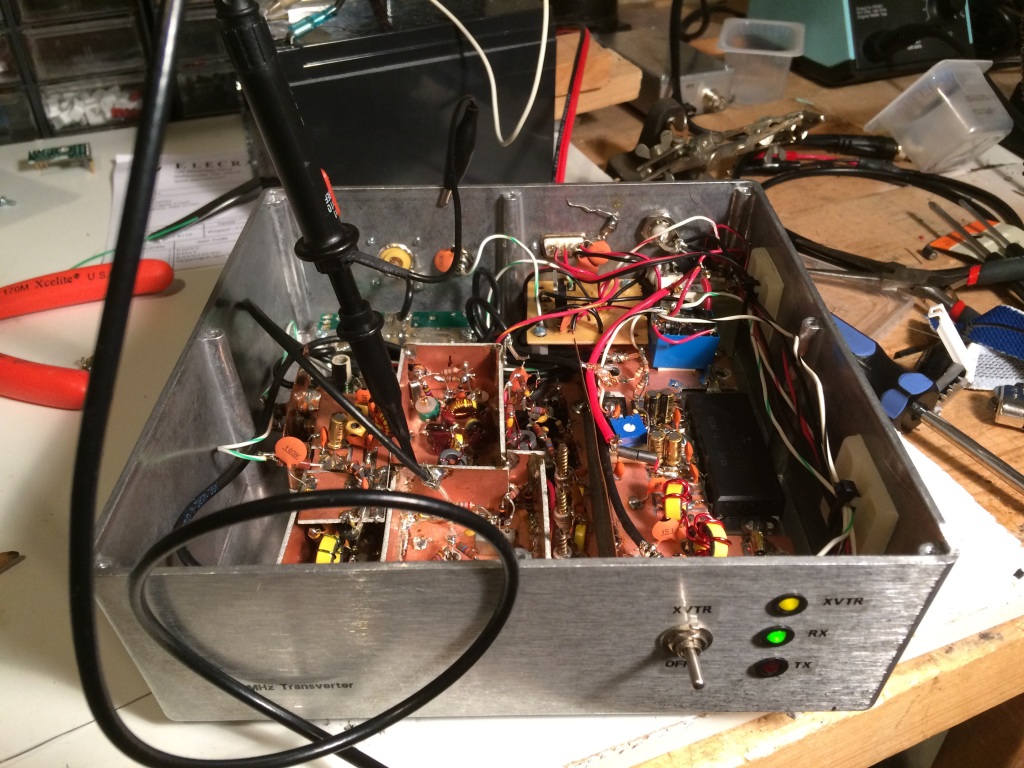
Worked D3AA on the third call on 30-meter CW last night.  So, I guess that antenna is working.  Also worked VP9GE on 6 meters. There’s a certain amount of satisfaction working DX with a transverter you designed (mostly) and built yourself.

I have a wicked RFI problem on 6 meters when I run the amp (150-watt Mirage brick).  It’s probably RF on the power lines, although it doesn’t set off the CO detector like 40 meters does.  So, it could be RF pick up on the audio wiring in my shack.  In any case, need to get that worked out before the ARRL June Es contest.

W1GHZ 903-MHz TX Gain Compression

March 5th, 2012

I managed to sneak into the lab again at lunch today for a few minutes and hooked up the now-packaged W1GHZ 903-MHz transverter to do a transmit gain compression test.  This test is a quick and dirty way to find the linear operating region of the transverter in addition to the expected conversion gain on transmit.  These two parameters determine the IF transmit level and what kind of power amplifier or driver stage will follow.  It’s an easy test to run if you have the equipment.  I locked the transverter in transmit by applying 8 volts to the TX MMICs and used a Rodhe and Schwarz SMR40 signal generator as the IF transmitter at 147.100 MHz.  On the transverter TX output, I simply connected the HP 8565E spectrum analyzer that I’ve used in the past.  Spectrum analyzers are not great power meters, but they give you a good enough idea of what’s going on.  The 1-dB gain compression point (that is, the point where the actual device gain sags 1 dB from the linear gain) is at an input of -3 dBm or an output of just under 10 dBm.  This compares favorably with the datasheet for the mixer and discussion with N3UM.

903-MHz cavity filter tune-up

February 28th, 2012

For reasons that will become clear in a future post or series of posts, we’ve been busy lately—don’t worry, it’s a good thing.  I did manage to sneak away from my regular (usually desk-bound analysis) work into the lab and tune-up an eBay-special cavity filter for 903 MHz with our new network analyzer.  It’s really amazing how you can dial these things in if you have the right tools.  This one is a 3-cavity filter about 10x8x3 cm.

Passband insertion loss is about 1.2 dB.  Harmonic rejection at 1.8 GHz is 70 dB down.  I’ll take it.

I also have some eBay-special helical filters that were advertised to be for 432 MHz.  So, I need to cobble up some carrier boards to try them out.  Another day, another project.

SoftRock Ensemble RXTX IF modification

November 12th, 2011

This is a pretty simple modification that converts a SoftRock Ensemble RXTX SDR RF interface board from “common-IF” (RX and TX share the same antenna port) to “split-IF” (RX and TX have separate ports).  Split-IF is the standard for high-performance transverters on the 50-, (70-), 144-, 222-, and 432-MHz amateur bands.

So, I had a look at the RXTX schematics (here, here, and here) and considered the following options for where to break the RX and TX portions of radio:

The purple dots were the first option.  Unfortunately, these locations on the actual printed circuit board were not easily accessible to miniature coax and this process would involve significant surgery to perform and restore the modification.  The second alternative I considered was the red Xs…jumpering over the BS170 PA transistors.  By this time, I was looking for a way to avoid butchering the original circuit too much.  So, I elected for option three, which was to install a second T/R switch at the antenna jack (golden circle).  This had at least two advantages, the first of which was being minimally invasive.  The big advantage, though, is that the radio could be operated at its design output and run through a fixed or step attenuator on the TX side to the transverter.  This meant that I would be assured of having a reasonably clean signal to work with if I configured the radio correctly.  It also meant that I could operate the radio as designed if I simply disabled the the second T/R switch and connected the antenna to the default port.

So, here is the modification that I came up with using parts I had in my junk box.  KB9YIG ships the Ensemble RXTX with a couple of spare BS170 FETs that can be used in place of the 2N7000.  I just had a lot of 2N7000s and thought I’d save the BS170s in case I ever burnt one in the RXTX.

The interface to the transverter is through a DB9 connector.  PTT for this transverter is +12 volts (as done with the TS-930S) on pin 6.  Pin 1 is ground.  Pins 2 and 3 are shorted together in the transverter cable connector to enable the modification in the SoftRock.  The right portion of the schematic with the relay driver and Omron G6Y relay is based on the T/R switch from W1GHZ’s “Multiband Transverters for the Rover” that I decided not use on the microwaves when I found a cheap source of SMA coaxial relays.  An I2C decoder would be great to put band data on the other pins to select a transverter (or transverter cascade for the microwaves).

The whole mess works great from a switching standpoint.  When I key the PTT on Rocky or PowerSDR, it switches the TX line and keys the transverter.  I’m a little ambivalent about the quality of transmitted signal that’s actually coming out.  I think it’s good enough if you live in a sparsely-populated area, but I have a lot of VHF neighbors that I’d rather not upset.  So, I need to do some more testing on this—a lot of it is getting the RXTX and PowerSDR configured correctly.  It appears that the I/Q channels are flipped on my sound card (Audigy 2 ZS) between transmit and receive.  I don’t know if that’s a wiring error in my breakout box or whether it’s normal.  Spectra to come at some point…

SoftRock Ensemble RXTX

November 11th, 2011

A few photographs of my latest tinkering—a SoftRock Ensemble RXTX.  This unit provides all of the hardware necessary to have a software-defined radio (SDR) transceiver that uses a computer soundcard for ADC and DAC.  It is available here as a kit.  They are kitted in batches of 20-100 every few weeks and usually sell out within 24-48 hours.

I originally had little interest in doing a full SDR transceiver (preferring receivers only) until it occurred to me that I could modify the RXTX as an IF strip for VHF/UHF transverters like many have done with the FlexRadio Systems rigs.  So, I have developed a modification that is minimally invasive to the operation of the RXTX.  At build time, you choose a nearly octave-wide “super band” for operation.  This one was built for the 20-30 MHz band, covering the 15-, 12-, and 10-meter Amateur bands, as well as the 25-28 MHz IFs that I (will) use with present and planned transverters for the 6-, 2-, 1.25-, and 0.70-meter bands.

I’m not sure I have the enthusiasm to build another SoftRock.  There are a lot of trifilar transformers to wind.  The final result looks pretty good and seems to work.  I’m going to put it on the spectrum analyzer soon to see how clean the output is and how I should balance the drive for the transverters.  Then, I will also include a write-up of how the modifications are done.  (I promise that writeup is the same place as the control circuit schematic for the 50-MHz transverter!)

Here, you can see the W1GHZ relay board for doing split-IF T/R switching.  If the transverter control cable (DB-9) is disconnected, the SoftRock switches to common-RF for regular 15-/12-/10-meter operation.

(No?) Nonsense Radio

November 10th, 2011

The November 2011 issue of QST contains an Op-Ed that really left me shaking my head more than normal.  The author bemoans the complexity and feature sets of newer handheld radios and pines for the days of his IC-02AT.  He goes on at length about the “unnecessary” receive capabilities (NOAA weather broadcasts, AM/FM radio, etc) and how he has to search for the manual every time he wants to program a repeater offset.

Well, as someone who recently upgraded from a radio just slightly newer than the IC-02AT to a “modern” HT, he’s wrong on nearly every account (except the micro-/mini-USB port, which I would wholeheartedly support for charging purposes).

  • Eliminate extraneous features.  Too bad we all have different definitions of this.  I think scanning is a worthless feature, but like NOAA/NWS weather broadcasts.  In fact, my wife is delighted that we now have a battery-powered AM/FM+NOAA/NWS radio again that I will always be able to find and will guarantee that it works.  Did you hear that, guys?  My non-ham wife actually likes my HT and uses it to listen to FM radio!
  • Eliminate multilevel menu trees.   I’m just dying to replace my cell-phone-sized VX-3r with a knob-covered brick.  I’m sure you are too.  It’ll look great in my shirt pocket.
  • Eliminate the proprietary programming cables.  Maybe I’m not a typical ham, but I only have about ten memory channels programmed into my VHF/UHF FM radios and they took about 10 minutes to program through the front panel (my bad, menus).  The mini-/micro-USB port is a good idea for charging, though.
  • Allow for a battery pack that uses disposable batteries.  Last time I checked, most radios have this option.  Did I miss something?
  • Create an inter-vendor standard for user interface.  What if they standardize on Icom?!?!  The last Icom VHF/UHF FM radio I used received a “grade of S, for ‘stupid'” from its owner.  That was in 1993.  All of the Japanese manufacturers will be put out of business by the factory owned by the Chinese military that produces their products before this happens.

He should buy another IC-02AT if he liked them so much.  I bet for a Jackson or two, you could have a nice one…complete with the 6x AA battery holder.  Heck, buy two or three for spare parts.  I think I have the Service Manual around here somewhere if I didn’t already sell it.

On a more serious note, there are lots of no-frills radios available out there, even brand new ones with factory warranties.  Until recently, at least, the money in VHF FM radios was in two-way, government, and public safety, not amateur.  There are a lot of amateur rigs at the “low end” of the market that share a lot in common with their commercial counterparts.  And, of course, you can always buy used Motorola gear on eBay if you desire ultimate performance and ruggedness.