I made another trip to American Sa’moa (KH8 for the radio amateurs in the audience) to deploy instrumentation. It was a tight timeframe but the instruments seem to work and I managed to make a few ham radio contacts as well.
-
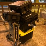
- Flock of Pelicans in Honolulu. Big overweight baggage bill.
-
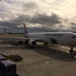
- Waiting to board 767-300ER from HNL to PPG.
-
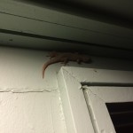
- Ubiquitous lizard
-
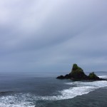
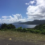
- Seascape on the road to Tula.
-
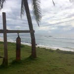
- Bell fashioned from a discarded gas cylinder, a common sight.
-
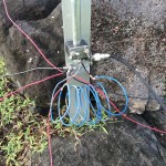
- Loading coil for the GU Special fashioned from wire I found on the side of the road (not joking). This made the radio happy on 40 meters.
-
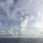
- Believe it or not, there’s a C-130 in this photograph.
-
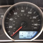
- Car says it was 90 F (32 C) outside.
-
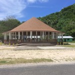
- Traditional Samoan home or “fale.”
-

- Requisite selfie from “today’s office.”
-
- Building infrastructure to support the experiment.
-
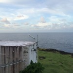
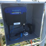
- Blockhouse for instrumentation (and radio shack) now with WiFi and GNSS antennas.
-

- We live in the future: Raspberry Pi computer plugged into hotel TV.
-
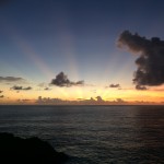
- Crepuscular rays from Cape Matatula.
-
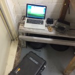
- Ham setup. I spent a lot of time sitting on Pelican cases.
-
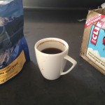
- Freezed-dried food is remarkably tasty…or I was hungry.
-
- Hammer (drill) time!
-
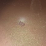
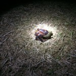
- Critter of the dark: Coconut crab the size of a basketball. Crabs this big are rare and prized for their tasty meat.
-
- Critter junior: coconut crab the size of a softball.
-
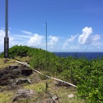
- Some of the research antennas.
-
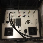
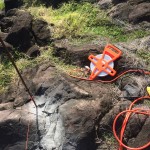
- Research receiver instrument.
-
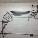
- Cable runs dressed.
-
- Beautiful.
-
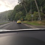
- Yes, that is a jacked-up Corolla.


