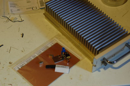
- Crystal oscillator for 98.5 MHz. Check.
- TUF-1 and TUF-3 mixers. Check.
- SMT protoboard. Check.
- MMIC amplifiers. Check.
- Larcan TV exciter amp. Check.
Do you see what I see? Yes, a 222-MHz transverter is on the horizon.
Do you see what I see? Yes, a 222-MHz transverter is on the horizon.
Late last Summer, it came to my attention that the 903-MHz W3APL beacon had gone off-line. The failure was intermittent and seemed to resolve itself after power was reset. Several efforts to troubleshoot it were undertaken by myself and others, including running it at high duty into a dummy load over a period of days. I was unable to get the problem to manifest itself on my bench.
A synthesized source (Analog Devices demo board) was offered by a friend of the Club, however it did not produce the desired output (or any output at all). It’s not clear whether this was the fault of the synthesizer or the user (me). The notional plan was to replace the beacon, which consists of a 75-MHz crystal oscillator followed by 12x of multiplication and a small RF power module, with the synthesizer and a new RF power module. The project languished, as they often do in my hands. But, two weeks ago I picked up the task again and made some real headway.
Really, the failure had to be one of a couple of things: 1. Intermittent connection exacerbated by thermal cycling. 2. Oscillator “unlock” due to component aging and thermal cycling. I reasoned that as long as we could eliminate #1, the multiplier chain and amplifier should be fine. The behavior seemed to point toward #2 or perhaps a combination of #1 and #2. I came across a forlorn Programmed Test Sources PTS-040 that I had rescued from another group’s surplus heap to put in my lab. I hadn’t used it in the two years that it was in my possession, so it seemed logical to provide it to the Club on a long-term loan. The problem was that it didn’t go up to 75-MHz. So, I cooked up a little multiplier chain. My “good” HP spectrum analyzer is on-loan to a paying program so I had to make do with the FFT function on the fastest Tektronix portable scope I had in the lab.
My initial effort at the multiplier chain was to build a 2N3904 amplifier that swung way into saturation producing a signal rich in harmonics. I went straight away for the 903-MHz signal but I couldn’t get a good enough lumped-element filter to eliminate the adjacent harmonics. So, I tried for the 75-MHz injection. This demanded a buffer amplifier so I lazily reached for the MMIC drawer in and retrieved one of the plentiful MAR-8s. Plenty of gain…and, as I would find out in a moment…conditionally stable! To exercise the eloquent euphemism of Ben, N3UM, the MMIC “burst into song” at about 63 MHz.
Back to the drawing board. I knew that I had something that would work, so I redesigned the deadbug layout on an SMD protoboard (the kind with all the pads in a grid). I replaced the discrete 2N3904 and MAR-8 MMIC amps with SGA-4586Z MMICs (which are a little too nice for this service, but I have a ton of them). Viola!
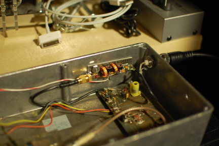
It’s the little board on the far wall of the diecast box with the SMA connector on the left and two toroids. 37-MHz RF comes in from the PTS-040 through the BNC jack in the wall. It’s multiplied up to 75 MHz on the new board and piped down to the remaining 12x multiplication and amplification stages before going to the little brick PA in the lower left (not visible).
So far, it sounds good. I was able to monitor it with my W1GHZ transverter strapped to the IC-290A in my car and using a WA5VJB cheap Yagi tossed in the back seat. I lost the signal about 5 miles away with that setup, which is really pretty decent all things considered at that frequency, etc, etc. Nominally, the frequency should be 903.054 MHz. I found it at about 903.048 MHz on the lash-up. Brian, ND3F (aka N3IQ/R) reported that he found it at 903.046 MHz with KA3EJJ’s setup. If you’re in the vicinity of FM19ne and are setup on 902/903, we’d appreciate a report. The big thing is the long-term stability. So, we’ll continue to monitor it.
Now…to get back to that 930 on my bench…
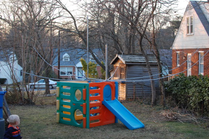
“What have you done to my play set?” This gym made a convenient place to string wires, etc. Two poles in the photo form part of the EWE RX antenna here at K8GU that was hastily erected before the NA Sprint CW. One of the poles is ty-wrapped to the play set. Doing my best to keep it klassy and impress the neighbors.
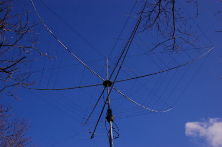
And, we’re up in the air! The M2 9M2SSB is a little bit out of alignment due to the hex getting tangled in one of the antennas that it was due to replace. I have already realigned that. So far, the antenna seems to have useful front-to-back. Gain is hard to tell since I took down all of the antennas it was to replace. But, it does seem to work. I’m suffering from high SWR (above 3) on both 21 and 50 MHz. G3TXQ warns of interaction between 18 MHz and 50 MHz. Do not yet know the cause, but I’m looking into it.
Although the antenna is relatively easy to handle, I don’t plan to make a habit of taking it down for work. Speaking of taking down, the 40m dipole whose center insulator is just visible behind the reflector of the 2-meter beam will be replaced by an as-of-yet-secret antenna.


Construction project: G3TXQ hex beam built from scratch. K4KIO directions with K8GU modifications (and reverse-engineered square coaxial center post). Details to follow once I determine it works to my satisfaction.
Heard this on the radio the other day on my way to work. Does it explain, at least in part, the popularity of Elecraft products?
In other news, the blog has been silent for a while, but that doesn’t mean things haven’t been happening. I have a couple of challenging projects that have been taking up the usual blogging time. Stay tuned!

I found myself in Santa Fe, NM, for Field Day this year to attend a conference. As I have shared before, I have mixed feelings about Field Day, but this was a genuinely good time. I first checked ARRL’s Field Day finder map and the local club’s web site for activity. Zilch. So, I remembered staying at the Fort Marcy Hotel Suites on several previous visits to Santa Fe. These condos are up on a hill overlooking town. Across the street is Hillside Park, with a couple of scraggly trees that might be suitable for antennas.
Instead of bringing the “usual” portable station, I brought a Small Wonder Labs SW-40, a K1EL K12 memory keyer (assembled especially for this trip), Palm Mini paddles, a 40-meter dipole, and a AA battery pack. The whole station took up less space in my luggage than my notebook computer and set up in 15 minutes. I got the dipole center about 4-5 meters off the ground and the ends sloped down to about 2-3 meters high…just enough to allow cars and small trucks to pass under them in the parking lot. Apologies for the photographs…they were taken with my cell phone (which is a regular old “dumb” phone).

The SW-40 did not appear to be transmitting correctly when I first hooked everything up. So, I pulled the cover off (packing a Leatherman tool is another good reason to check a bag) and wiggled some wires around until it fired up. Not an auspicious sign.
But, I did manage to operate for about an hour and make 12 or 15 QSOs. They’re logged in a notebook, but I haven’t looked at it since making the contacts. Virtually every QSO was a struggle. Low power (1.5 watts), wrong band (20 meters would have been better), a low antenna, and the fact that I hadn’t used the SW-40 for any QSOs in over 10 years, conspired to make thing difficult. Most operators pulled me right out once I was in the clear and zero beat (which I think was a serious challenge with the slightly drifty and definitely touchy SW-40).
My final QSO was with my old radio club from my college days, W8FT. The operator was my good friend Bill, AD8P, who worked hard to pull me out once he got my call right. After I packed up, I noticed that I had a missed call on my phone…sure enough it was from Bill. So, I gave him a call and we talked for a couple of minutes. “When he answered the phone, he said, `New Mexico?!?! I told Kelsey (N8ET) that’s what I had copied.'” We had a nice chat as I hiked back down the hillside into town and he pulled into his driveway after his FD shift.

I don’t think I’ve ever been so delighted with a Field Day effort of so few QSOs (except maybe my first Field Day, which was much more work for about twice the number of QSOs). Including the walk from my hotel to the park, setup, tear-down, and operating, I think the whole exercise took about 3 hours, and was tremendously FUN.
With the loss of my preferred frequent flyer status, airlines tightening their checked luggage allowances, and the addition of another traveler to the family, I’ve been contemplating a new portable antenna that is easier to pack than my usual DK9SQ mast and dipoles. I don’t do high-priced reduced-size antennas if at all possible since portable installations usually have other efficiency-reducing problems. Multi-element antennas take up additional space and have feeding and installation complications that are unnecessary for the casual DX operator. So, that leaves us to choose between a vertical and a dipole.
A few words about efficiency: Dipoles have a distinct efficiency advantage over verticals in almost every practical installation for 40 meters and up, except when the vertical is physically placed in or over salt water. Radiation efficiency tends to be dominated by near-field conditions, pattern is dominated by stuff that’s farther away. This is why vertical dipoles work so well for long-haul DX when placed within a few wavelengths of salt water. They don’t need the near-field efficiency enhancement as much as base-fed verticals, but they still leverage salt water for developing their far-field radiation pattern, especially at low angles required for long-haul communication.
I’m a casual DX operator, not a DXpeditioner, so I never operate on 160 or 80 meters. That is, considering the discussion above, why I have been using dipoles with the DK9SQ. But, verticals have a distinct advantage over dipoles in the sense that they are self-supporting. I decided to build a vertical because: 1) my next DX trip would include time near a beach and 2) I wanted to be able to bring my own support as I had with the DK9SQ.
My remaining requirements were now simple:
And this is what I came up with:

There are 21 aluminum sections, most with a “swaged” (actually, a poor-man’s swage to be described in a moment) end and a slit end. They are shown here bundled perfectly inside a section of cardboard shipping tube. An 18 x 2.5 x 0.125-inch aluminum plate serves as the base. I used DX Engineering resin support blocks to insulate vertical from the base. A point could be fashioned on the bottom of the base and a foot plate attached to push into soft soil, but that has not been done.


Most sections fit together using overlapping joiner pieces that I previously referred to as “poor-man’s swaging.” I’m not sure that it’s actually a savings over paying a local shop to swage the ends for you when time is considered in addition to material, but I cut telescoping pieces six inches long and fastened them three inches deep in one end of a 17-inch section of tubing with two offset and orthogonally-placed aluminum pop rivets for a total length of 20 inches. This geometry not only fits in my suitcase, but results in a very small amount of wasted material as well.

The other end of each piece is slit about 2 inches and they mate with an all-stainless steel hose clamp. The first 10 feet of the antenna are 0.75-inch 6063-T832 tubing followed by telescoping sizes down to 0.375-inch at the very top. The transition pieces are a full 20 inches long and are slit on both ends. The full-size antenna will stand in a light breeze, but guying is a good idea. Guy rings are fashioned out of flat washers drilled in three places.
Tune-up is easy…the more radials you use, the less critical their length. After about 8 or 10, you’re in the clear here. I never attached enough to prevent them from affecting the tuning. If you only plan to have a couple of radials, go ahead and cut them to 1/4 wavelength (even though ground proximity will detune them). Then, set the length of the antenna using the required number of 17-inch sections (the 234/f formula is surprisingly close) with the last section being a variable length for fine tuning.
I’ve intentionally left out most of the details of the antenna itself because I don’t expect anyone duplicate it exactly. But, here are a few notes for anyone considering building one themselves:
That’s it. The antenna goes up in a few minutes, especially if not used at full length. I used it successfully last week as OA5/K8GU, which will be detailed in a future post.
This is a pretty simple modification that converts a SoftRock Ensemble RXTX SDR RF interface board from “common-IF” (RX and TX share the same antenna port) to “split-IF” (RX and TX have separate ports). Split-IF is the standard for high-performance transverters on the 50-, (70-), 144-, 222-, and 432-MHz amateur bands.
So, I had a look at the RXTX schematics (here, here, and here) and considered the following options for where to break the RX and TX portions of radio:

The purple dots were the first option. Unfortunately, these locations on the actual printed circuit board were not easily accessible to miniature coax and this process would involve significant surgery to perform and restore the modification. The second alternative I considered was the red Xs…jumpering over the BS170 PA transistors. By this time, I was looking for a way to avoid butchering the original circuit too much. So, I elected for option three, which was to install a second T/R switch at the antenna jack (golden circle). This had at least two advantages, the first of which was being minimally invasive. The big advantage, though, is that the radio could be operated at its design output and run through a fixed or step attenuator on the TX side to the transverter. This meant that I would be assured of having a reasonably clean signal to work with if I configured the radio correctly. It also meant that I could operate the radio as designed if I simply disabled the the second T/R switch and connected the antenna to the default port.
So, here is the modification that I came up with using parts I had in my junk box. KB9YIG ships the Ensemble RXTX with a couple of spare BS170 FETs that can be used in place of the 2N7000. I just had a lot of 2N7000s and thought I’d save the BS170s in case I ever burnt one in the RXTX.

The interface to the transverter is through a DB9 connector. PTT for this transverter is +12 volts (as done with the TS-930S) on pin 6. Pin 1 is ground. Pins 2 and 3 are shorted together in the transverter cable connector to enable the modification in the SoftRock. The right portion of the schematic with the relay driver and Omron G6Y relay is based on the T/R switch from W1GHZ’s “Multiband Transverters for the Rover” that I decided not use on the microwaves when I found a cheap source of SMA coaxial relays. An I2C decoder would be great to put band data on the other pins to select a transverter (or transverter cascade for the microwaves).
The whole mess works great from a switching standpoint. When I key the PTT on Rocky or PowerSDR, it switches the TX line and keys the transverter. I’m a little ambivalent about the quality of transmitted signal that’s actually coming out. I think it’s good enough if you live in a sparsely-populated area, but I have a lot of VHF neighbors that I’d rather not upset. So, I need to do some more testing on this—a lot of it is getting the RXTX and PowerSDR configured correctly. It appears that the I/Q channels are flipped on my sound card (Audigy 2 ZS) between transmit and receive. I don’t know if that’s a wiring error in my breakout box or whether it’s normal. Spectra to come at some point…
A few photographs of my latest tinkering—a SoftRock Ensemble RXTX. This unit provides all of the hardware necessary to have a software-defined radio (SDR) transceiver that uses a computer soundcard for ADC and DAC. It is available here as a kit. They are kitted in batches of 20-100 every few weeks and usually sell out within 24-48 hours.

I originally had little interest in doing a full SDR transceiver (preferring receivers only) until it occurred to me that I could modify the RXTX as an IF strip for VHF/UHF transverters like many have done with the FlexRadio Systems rigs. So, I have developed a modification that is minimally invasive to the operation of the RXTX. At build time, you choose a nearly octave-wide “super band” for operation. This one was built for the 20-30 MHz band, covering the 15-, 12-, and 10-meter Amateur bands, as well as the 25-28 MHz IFs that I (will) use with present and planned transverters for the 6-, 2-, 1.25-, and 0.70-meter bands.

I’m not sure I have the enthusiasm to build another SoftRock. There are a lot of trifilar transformers to wind. The final result looks pretty good and seems to work. I’m going to put it on the spectrum analyzer soon to see how clean the output is and how I should balance the drive for the transverters. Then, I will also include a write-up of how the modifications are done. (I promise that writeup is the same place as the control circuit schematic for the 50-MHz transverter!)

Here, you can see the W1GHZ relay board for doing split-IF T/R switching. If the transverter control cable (DB-9) is disconnected, the SoftRock switches to common-RF for regular 15-/12-/10-meter operation.


After about six years of sporadic effort, I finally finished the W3NQN filter set by building the 10- and 15-meter filters over the past two weekends. Now I can operate SO2R with impunity on all bands. Several band combinations are still problematic, but those are problems that filters can’t solve.

Because the geometry of our home does not permit me to have a walk-behind station desk, I had to attach the filters to the mounting board by laying on my back with a right-angle drill. That sort of thing is always a bit exciting!
© 2025 k8gu.com · Proudly powered by WordPress & Green Park 2 by Cordobo.
Valid XHTML 1.0 Transitional | Valid CSS 3
![]()