Posts Tagged ‘cheap VHF’

W1GHZ 903 MHz RX working!

November 16th, 2010

Although I built the W1GHZ 903-MHz transverter and 756-MHz LO boards last winter, I didn’t have time or inclination to test them until this week.  These were purchased as a part of the first (October 2009) group buy orchestrated by W8ISS.  Instead of the INA-10386 MMIC recommended by W1GHZ, the W8ISS kits featured a Sirenza SGA-3586Z MMIC as the LNA, as suggested by the 4s_microwave group.  A better part (with NF < 2 dB), recommended to me by W9SZ, is the the SGA-4586Z, which I used on my 903 board and will use on my 1296 board.  This requires the bias resistor (R3, 51 ohms, on the 1296 board) to be changed to 100 ohms.

Since there is a lot of foliage between me and the W3APL beacon, I took the liberty of carting the transverter and IF rig to the beacon site (sorry no photos) on my lunch break yesterday.  Sure enough, it worked like a charm with the beacon pounding in on 147.0615 MHz.  The nominal beacon frequency is 903.055 MHz, so I don’t know if the difference is in my LO or the not-GPS-locked beacon drifting around.  At any rate, I’m pleased enough to continue the project…

The 1296RSU transverter and 1152-MHz LO boards are on the left in the photo above.  They have not yet been populated, but that’s an evening’s work.

Keyboard Trays, QRP Rig, and SoftRocks

October 18th, 2010

Time, as they say, has been of the essence of late.  So, when I do have time to play radio, I rarely have a chance to write about it.  Here are some photos of my latest tinkerings.

Keyboard Trays

Sarah has always talked about using a keyboard tray at work as a part of an ergonomic workstation.  Until recently, my work invovled enough variety of computer and non-computer time that I did not think about it.  But, after coming home from work with stiff shoulders and wrists, I decided something should be done.  While I was at it, I upgraded the HF and VHF/SDR operating positions at K8GU with pull-out trays, as well.  These were $10 each at IKEA and pretty easy to install, although I told Sarah that I was grateful that she didn’t witness my contortions to hold them up with my knees while driving the first screws.

Liberating my inner QRPer

Back in high school, I built a Small Wonder Labs SW-40 that I had seen in a QST article.  It lived in a variety of enclosures, but spent the last decade in the ugly PC board half-enclosure that looked like a redneck pickup truck at right.  I decided to put it into a proper enclosure, being the diecast box at left.

Despite the fact that I made the radio impossible (no room for front panel controls) to assemble the first time I drilled the board mounting holes, I’m pleased with the result.  Four dabs of gray epoxy cover the errant holes.  I probably could sand and polish those now.  The power connector is a pair of Anderson Power Poles.

VHF Softrock and Enclosures

Readers of the blog have seen the screen capture from my new Softrock Ensemble II VHF.  Tony does not advertise these on his site because they are not 100% supported with documentation yet.  Robby, WB5RVZ has done a great service to the community by preparing step-by-step instructions for most of the SoftRock series.  I’m not a step-by-step kind of guy, so I just used his photos showing the locations of the 0.1 uF and 0.01 uF chip capacitors and built the rest my way:  mount all chip caps, all SMT ICs, all through-hole ICs and sockets, all through-hole resistors and diodes, all through-hole capacitors, all inductors, and all connectors.  It worked right away.

I also have two v6.0 SoftRocks that I built a few years ago while I was in grad school.  One of these (for 160) has been a bare board all these years and the other (for 40 and 80) has been living in an ugly little RadioShack black plastic project box.  I decided to upgrade them to diecast boxes with external power connectors (also PowerPoles—I’m slowly switching the station over) and a switch for 40 and 80 meters.  Here’s the happy family of little radios…

The 160-meter SR v6.0 is on top of the diecast box holding the SR v6.0 40/80.  The Ensemble II VHF is on the right.  It’s unfortunately too long for either size diecast box.  I don’t like the commercially-available box for it.  So, we’ll have to see…

144-MHz SoftRock

October 14th, 2010

144-MHz SoftRock Ensemble II VHF by KB9YIG and VE3NEA Rocky 3.6.  Yup, that’s W3APL/B (off the back of the beam) and WA1ZMS/B in the same waterfall.  How cool is that?!  More later…  This has many implications for many projects!

VHF/UHF firepower

September 16th, 2010

As if I don’t have enough projects already, I recently obtained these two surplus FAA AM-6155 amplifiers on, as usual, very attractive terms.  I don’t have the equipment to properly test them at this point.  But, that is coming.  The FAA specified these to do 50 watts continuous duty AM.  With modification, they will do about 300-400 clean watts with 10 watts of drive on 144, 222, and 432 MHz.  Once I get the first two working (on 222 and 432), I plan to find two more of them and use them on 50 and 144 MHz.  For 50 MHz, I plan to remove the VHF/UHF cavity and components and install an RF deck using the same Amperex DX393 or Eimac 8930 tube.  Comments and ideas welcome.  They’re a lot cheaper than bricks!  One of my units appears to be at least partially converted already, but I’ve only had it open for a few minutes with my brother Seth, who got all of the mechanical aptitude in the family.

Note:  Thanks to WY3X for catching my error on the tube type.  He also notes that 300 watts would be a conservative maximum on 432.  I plan to run the amps with very low drive after tuning so I can compete in the ARRL’s low power category at 100 watts on 222 and 432.

Super-sizing the “cheap Yagi” (Part 2)

August 4th, 2010

The two most expensive parts of a VHF/UHF Yagi are the boom hardware and the feedpoint.  So, I set about eliminating these costs, keeping in mind that I may only have the antenna installed for a year or two at this QTH.

The feedpoint mechanical construction has been addressed in a previous note.  However, I should back up and discuss changes from the K1FO Yagi.  In its original configuration, the K1FO antenna is fed with a T-match.  This is mechanically complex, although some might argue that it’s sturdier than my solution.  I elected to feed the antenna with the WA5VJB hairpin design (38-inch element with harpin 1/4-wave stub spaced 1 inch for 19 inches—this is just a convenient and inexpensive ruse for direct feed without splitting the driven element) for the moment.  Yes, I am aware that the K1FO antenna has a natural input impedance considerably lower than 50 ohms, but this is just the first (essentially mechanical) prototype.  I’ll do some modeling eventually and determine if I can or should optimize it further.

There are four choices for a boom:  PVC pipe, fiberglass, aluminum, or wood.  PVC is heavy and too flexible for anything longer than two or three feet.  (I see people asking questions in forums all the time about building antennas out of PVC.  Why bother when wood and aluminum are so readily-available?)  Fiberglass is light and strong, but unless you have access to a lot of it, it’s the most expensive of these options and the most difficult to work.  That leaves aluminum and wood.  Aluminum is hard to beat for strength-to-weight ratio and ease of working.  But, wood will give it a run for its money on cost for a reasonable strength up to a point.  Since I had a bunch of wood readily available, I elected to build the boom from wood.  This is probably pushing the practical upper limit for a wood-boom antenna.

For the boom, I used three pieces of 1 x 2 select pine that was weatherproofed with a clear lacquer:

The 0″ reference point for the element position measurements is at the left end.  Don’t forget to leave a couple of inches at the end.

The original WA5VJB designs were optimized for 1/8-inch diameter elements, which is fortunately quite inexpensive (part #8974K14, $2.11/each, working out to a $12.66 antenna, plus about $5 for shipping…you can buy a lot of Al rod and still ship it for $5.) from McMaster.  The K1FO designs are provided for 3/16- and 1/4-inch elements, costing $4.13 or $6.03 for six-foot pieces respectively.  That was a little rich for my budget, but then I looked at the Metric-dimensioned 6061 aluminum rods.  5 mm is a little more than 3/16 inches and these rods are only $1.64/each ($19.68 for 12 six-foot lengths; examining the element length table below should give you an idea how much savings there is if you get some buddies together to build a few of these…forget buddies, build an EME array)!  So, I built the antenna out of 5-mm diameter rods using the 3/16-inch dimensions.

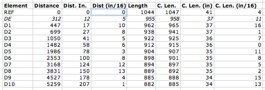
The table contains initial element lengths and offsets in inches.  Do not build this antenna! (Do as I say, not as I do.)  It appears to be a good performer, but it has not yet been optimized as discussed above.  The columns “Dist (in)” and “Dist (in/16)” refer to the integer and fractional portions of the distance, respectively.  Likewise, “C. Len. (in)” and “C. Len (in/16)” refer to the element lengths.

Using a cheap Dawia SWR meter at the end of the feed cable, I can tell that the SWR is less than 1.7 across the low portion of the band.  Actually, it’s relatively flat around 1.5-1.7 all the way up to 144.5 MHz where I quit measuring.  The pattern is apparently good.  My “local” beacons that I can pretty much always count on are WA1ZMS (to the southwest) and W3APL (to the northeast).  WA1ZMS runs a lot of gas to an excellent antenna system from an even more excellent QTH.  I can fade either of them into the nulls when listening to the other.  When I turn the antenna, they fade pretty rapidly into the noise, as well. Good F/B, F/S, narrow forward lobe, etc.

So, the upshot is:  I built the unmodified K1FO-12 design for 144 MHz on a wood boom for $30 and about 5 hours of tinkering with basic hand tools.  I can turn it and my 3-element 50-MHz Yagi with a 60-year-old CDE TR-2 TV rotor.  My TS-700S happily blasted 10 watts into it even at SWR of 1.7.  I’ll need to verify the cable loss and determine if my newly-acquired Mirage B3016 will tolerate it.

I will post models and photos eventually (once I find the files again…oops) for the 11-element disaster and the 12-element one I built.  Yagis are tricky to optimize well.  So, I’m somewhat disinclined to mess with the K1FO design and more likely to switch from the WA5VJB driven element to the T-match if I decide that the SWR matters that much.

Super-sizing the “cheap Yagi” (Part 1)

August 4th, 2010

One of the frustrations of doing VHF on the cheap is getting enough gain to make your low-power signal loud (or simply being heard) at the other end.  I had a couple of options with my 6-element WA5VJB “cheap Yagi” on 2 meters:

  1. Increase the height of the antenna. This is impractical at the present QTH without installing a tower.  Actually, the tower would have been possible but I wasn’t ready shoot first and ask questions later with it.  Nor was I ready to have my folks spring some Rohn 25G out of storage in their garage for the trip here when I had the opportunity (a truck bringing some furniture from them).
  2. Run lower-loss cable. I have regular old RG-8 (PE dielectric) running up to the antenna.  It’s only about a 50-ft run.  So, I’d be hard-pressed to do a lot better.  I did figure out how to recycle improperly-installed N-connectors for LMR-600 from a dumpster-diving excursion.  Although I have twenty-some connectors, I haven’t yet secured any scraps of LMR-600 to use.  This is a future consideration.  At $1.50/ft, LMR-600 would still cost $75.  No deal.
  3. Stack multiple 6-element antennas. This is actually a good idea that I’m keeping in the back of my head for the future.  It would be nice to do something like this.  Maybe some day.
  4. Launch a rocket to do a chemical release whenever/wherever I needed a sporadic-E layer.  Unfortunately, you can’t launch rockets over land.  (Update:  I was reminded later that this is not 100% correct.)  Furthermore, at a megabuck per shot, it’s not cost-effective.
  5. Dispense with the 6-element design and go for something bigger.

I elected option #5.

The first step was to consider suitable designs.  I tried scaling the 11-element 432-MHz cheap Yagi to 144-MHz.  Fail.  A NEC model showed that the pattern stunk and the input impedance was pretty far from 50 ohms.  Knowing that W5UN had built an array of wood-boom antennas for his EME setup, I looked into readily-designed options.

The ARRL Handbook (1993 edition for reference) and ARRL Antenna book (18th edition) have the K1FO optimized Yagi designs in them.  This antenna has been around for a number of years (clearly) and is available commercially from Directive Systems.  It seemed like a relatively good choice.  So, I moved forward with it…

Feeding the WA5VJB cheap Yagis

July 30th, 2010

The WA5VJB cheap Yagis are a great way to get on VHF/UHF without spending a fortune on commercial antennas.  While it is practical on the UHF/microwave bands to use a copper driven element, it is less practical on the 144 and 222 MHz bands.  I know that McMaster carries copper and brass rods, too.  But, I also like to have a coax connector at the feedpoint.  Since I am in the process of building what amounts to a “super cheap Yagi” (note that’s not a “super-cheap Yagi,” the hyphen matters; will report on this in the future), I figured I would share my feedpoint for aluminum driven elements.

While wandering through the electrical aisle of the local big box hardware retailer about six months ago, I discovered the Thomas and Betts ADR6-B2 (try the ADR6 for a drawing of a similar part) grounding lug.  This looked like a good candidate for the cheap Yagi feedpoint, especially costing only $1 for a pair.  In order to fit an SO-239 flange-mount connector to the ADR6-B2, I cut off the portion of the lug with the bolt hole and drilled my own hole (#43) and tapped it 4-40.  I did the same to the other piece.  I did not cut off the lug on the second one, but I should.  Then, I soldered a short piece of wire to the center conductor of the SO-239 jack and added a lug to it.  Here are the parts so far:

Then, I assembled the whole mess on the J-shaped driven element (dummy used for photos) using two 3/8″ 4-40 screws and a lock washer.  Note that the ADR6 lugs are installed on opposite sides of the element.

And, after installing on the wooden boom, it looks like this:

It’s not quite square and some mechanical strengthening is in order before it goes up in the air.  But, this is a considerable improvement over what I’m using now.  Ty-wraping the coax to the boom will provide considerable relief to the connector and it’s attachment.  More details will be forthcoming on the antenna, if it works.  Stay tuned!

IC-290H dial frequency offset

July 5th, 2010

Some time back, I had the good fortune to stumble across a broken IC-290H at an attractive price.  The IC-290H is a synthesized mid-1980s 25-watt 2-meter all-mode transceiver.  Since I had been contemplating a radio to use as the IF to my W1GHZ transverters for 903 through 3456 (yeah, still need to build/integrate all of these), I jumped.  The problem was described as an offset of some tens of kHz between the dial frequency and the actual transmit and receive frequencies.  Since the IC-290 lacks a user community like the TS-600 and TS-700 (my other 2-meter all-mode radio), I went to Google and then posted a quick inquiry on the Stanford VHF e-mail list to see if this was a common problem.  Google produced nothing and the VHF list produced the usual “get the Service Manual” response.  Since I already had the Service Manual thanks to the previous owner, I was set.

The synthesizer (“PLL”) in the IC-290H has at its heart a VCXO (shown above).  The control voltage biases varactor diodes D2 and D3 in a tank circuit with crystal X1 operated between the series and parallel resonant frequencies (as a very high-Q inductor).  Contributions to the control voltage come from the microprocessor (red dot), the receive incremental tuning (RIT, blue dot), and an overall bias of -9 V derived from 5 V using DC-DC converter IC2.

In the “PLL Adjustments” section of the Service Manual, the VCXO adjustments are outlined, checking the synthesizer output with a frequency counter.  I noted that as I changed rotated the VFO encoder on the front of the radio and the digits changed on the display, the output frequency of the synthesizer changed accordingly.  Similarly, the RIT caused the frequency to shift.  Neither of these things were surprising since I could tune in different stations before.  In USB mode at 145.998.5 MHz, the synthesizer should output at 134.250.0 MHz.  I read it at 134.230.21 MHz, clearly the source of the almost 20-kHz offset.  I nudged potentiometer R2 (against the vehement warnings of the Service Manual) and the output didn’t change.  For good measure, I swept R2 over its entire extent with no change.

R2, it seems, controls amount of the available -9 V bias applied to the varactors.  I checked the -9 volts line.  Zero.  Who stole the bias from the cookie jar?  The 5 V line was sagging down to 4.23 V.

I removed IC2, which is in a metal can that resembles an overgrown Mini-Circuits mixer and has only “DP-1” stamped on the cover in black ink.  For kicks, I drove this little guy with 5 volts into no load and got well over -100 V out.  Did this punk destroy other parts in my synthesizer?  I put this question to Dad, who happened to be here over the weekend.  He suggested that it might require a load to produce a regulated output.  Good thinking.  Nothing on the synthesizer board appeared to be charred.  So, my theory was unlikely and I proceeded.

Without IC2, the 5 V line bounced up to 4.95 V.  And, the output side (connected to L6) showed a DC short to ground.  If you trace the circuit from the output of IC2 to one of the legs of R2, nothing should show a DC short.  I looked for bridged solder traces.  None.  Taking the divide an conquer approach, I removed R10 (green dot), to isolate the entire RF portion of the circuit.  Still shorted.  So, this left the following three suspects:  two 0.1 uF ceramic disk capacitors and a 10 V, 100 uF electrolytic.  Since electrolytic capacitors, especially older ones, have a bad reputation for causing problems, I interrogated it first (C20, purple dot).  Bingo.

The only 100 uF capactor I had on hand that even came close to fitting was a 50 V unit from a previous repair.  I squeezed it in—it’s the big brown one against the edge of the case in the center of the photo below.  Note IC2 “DP-1” in the lower right corner.

So, I plugged the radio into a power supply and antenna.  And, low and behold…it was about back on frequency.  So, I completed the synthesizer and RIT adjustments in the Service Manual and put it back together.  It actually receives WA1ZMS/B on 145.285.0, which, Doppler notwithstanding, is GPS-locked at 145.285.000…   Stay tuned for the low-drive transverter IF modification in the next few months once I start building them again.

50-MHz Progress

June 14th, 2010

As I mentioned in the previous post, I’ve made some strides toward getting on 6 meters over the weekend.  I assembled the 3-element Yagi last weekend.  It was leaning against a post in our back yard pointing skyward for a few days.  I told Sarah that I was thinking of adding 18,431 more of these antennas so I could compete with the 50-MHz radar at Jicamarca.  She was not amused.  I hadn’t even mentioned anything about megawatts.  Yes, Virginia, the mast in the photo is not square.  The top portion of the mast is a little skewed in the rotor and it’s attached with rusty U-bolts that I’ve never loosened.  I’m still turning the antenna with the TR-2, even though I have a T2X out here now.  I will do that swap eventually.  But, for right now, the TR-2 is doing fine.

In order to start moving the transverter toward its new home in a beautiful rack-mount enclosure that previously housed a 900-MHz digital repeater (not included when I obtained the box, unfortunately), I had to “re-arrange its internal organs”, as a menacing extraterrestrial used to say in Space Quest.  Sarah wonders why I schlep all of this crap from place to place with us.  I’ve had that rack-mount box longer than we’ve been married!  It was just waiting for a chance to serve in my shack.  Anyhow.  You can see the layout above.  Sarah says it looks like a doll house.  Pretty sweet house, if I say so myself.

Here’s another view of the partially-integrated box.  I’m running it off a battery because I don’t have the power supply subsystem installed in the box, yet.  It’s really just a PA and some control circuitry away from operational.  Although, I would like to align the TX side with a spectrum analyzer at some point.

I heard quite a few signals in the ARRL contest over the weekend.  W5ZN comes to mind, as well as a couple of locals like N4QQ, who lives just a stone’s throw away on the other side of the Beltway (aka the wrong side of the tracks).  I suspect that the locals would move the S-meter a little more (like past S9) if I put an IF amplifier in after the RX mixer.  But, I’m not really keen to do that unless I have to.

Schematics will come once I’m finished.  But, nothing about this so far has been rocket science (or brain surgery, as the rocket scientists say).  I’ve just been following the Handbook.

Magic: right place, right time

June 13th, 2010

I put the 3-element 50-MHz Yagi (Cushcraft A50-3S) up yesterday morning with the 6-element 144-MHz Yagi (WA5VJB design) above it—just in time for the ARRL June VHF contest!  The 50-MHz transverter is not yet complete, although I have the RX side done and the TX side makes about 250 mW.  It’s not integrated and I haven’t started building the PA.  Bummer because yesterday was a pretty good Es day from what N3OX told me last night.

With 10 watts from a TS-700S to a 6-element Yagi at 30 feet, there’s not a whole lot you can work on 144 MHz.  Plus, everybody was on 50 MHz, so I could only hear the multi-operator and serious single-operator stations on 144 MHz locally.  Around 21:00 local time, Sarah and I had just returned from a walk.  I had pointed the beams WSW (my best shot from here is SW) and was slowly tuning up and down the band hoping for some tropo enhancement or something…and after a few passes, I heard on 144.210 MHz…

“CQ contest, CQ contest, looking for sporadic-E on two meters, CQ contest, Kilo Five Quebec Echo…”

That’s something alright!  I figured the beam was in approximately the right place and gave him a call.  He came right back and we exchanged grids.  He was there for a few minutes and then disappeared as suddenly as he had appeared.  I know he made at least one other QSO, but he was starting to fade by that point and I couldn’t hear the other side.  Cool!

My logging software calculated the great circle distance as 1037 miles (1669 km) between FM19 (me) and EM31 (him).  Either it was one heck of big meteor or (more likely) one heck of a sporadic-E opening.  Either way, I’m pleased.  Want more of that!