Posts Tagged ‘ic290’

W3APL/B 903-MHz beacon

May 7th, 2013

Late last Summer, it came to my attention that the 903-MHz W3APL beacon had gone off-line.  The failure was intermittent and seemed to resolve itself after power was reset.  Several efforts to troubleshoot it were undertaken by myself and others, including running it at high duty into a dummy load over a period of days.  I was unable to get the problem to manifest itself on my bench.

A synthesized source (Analog Devices demo board) was offered by a friend of the Club, however it did not produce the desired output (or any output at all).  It’s not clear whether this was the fault of the synthesizer or the user (me).  The notional plan was to replace the beacon, which consists of a 75-MHz crystal oscillator followed by 12x of multiplication and a small RF power module, with the synthesizer and a new RF power module.  The project languished, as they often do in my hands.  But, two weeks ago I picked up the task again and made some real headway.

Really, the failure had to be one of a couple of things:  1.  Intermittent connection exacerbated by thermal cycling.  2. Oscillator “unlock” due to component aging and thermal cycling. I reasoned that as long as we could eliminate #1, the multiplier chain and amplifier should be fine.  The behavior seemed to point toward #2 or perhaps a combination of #1 and #2.  I came across a forlorn Programmed Test Sources PTS-040 that I had rescued from another group’s surplus heap to put in my lab.  I hadn’t used it in the two years that it was in my possession, so it seemed logical to provide it to the Club on a long-term loan.  The problem was that it didn’t go up to 75-MHz.  So, I cooked up a little multiplier chain.  My “good” HP spectrum analyzer is on-loan to a paying program so I had to make do with the FFT function on the fastest Tektronix portable scope I had in the lab.

My initial effort at the multiplier chain was to build a 2N3904 amplifier that swung way into saturation producing a signal rich in harmonics.  I went straight away for the 903-MHz signal but I couldn’t get a good enough lumped-element filter to eliminate the adjacent harmonics.  So, I tried for the 75-MHz injection.  This demanded a buffer amplifier so I lazily reached for the MMIC drawer in and retrieved one of the plentiful MAR-8s.  Plenty of gain…and, as I would find out in a moment…conditionally stable!  To exercise the eloquent euphemism of Ben, N3UM, the MMIC “burst into song” at about 63 MHz.

Back to the drawing board.  I knew that I had something that would work, so I redesigned the deadbug layout on an SMD protoboard (the kind with all the pads in a grid).  I replaced the discrete 2N3904 and MAR-8 MMIC amps with SGA-4586Z MMICs (which are a little too nice for this service, but I have a ton of them).  Viola!

w3apl_b_903

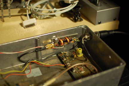
It’s the little board on the far wall of the diecast box with the SMA connector on the left and two toroids.  37-MHz RF comes in from the PTS-040 through the BNC jack in the wall.  It’s multiplied up to 75 MHz on the new board and piped down to the remaining 12x multiplication and amplification stages before going to the little brick PA in the lower left (not visible).

So far, it sounds good.  I was able to monitor it with my W1GHZ transverter strapped to the IC-290A in my car and using a WA5VJB cheap Yagi tossed in the back seat.  I lost the signal about 5 miles away with that setup, which is really pretty decent all things considered at that frequency, etc, etc.  Nominally, the frequency should be 903.054 MHz.  I found it at about 903.048 MHz on the lash-up.  Brian, ND3F (aka N3IQ/R) reported that he found it at 903.046 MHz with KA3EJJ’s setup.  If you’re in the vicinity of FM19ne and are setup on 902/903, we’d appreciate a report.  The big thing is the long-term stability.  So, we’ll continue to monitor it.

Now…to get back to that 930 on my bench…

Microwave updates

June 25th, 2011

Apologies for the bad pun in the title.  I was going to call it “Microwave progress” but could help myself when I thought of this one.  Here are some notes from tinkering over the past few days.

1296 Mhz

After learning that the 1152-MHz LO power was -11 dBm, I inserted a MAR-3 MMIC on the 1296RSU transverter board.  W1GHZ shows an MAR-6 on his board, but the ever-astute N3UM noticed that the P1dB for the MAR-6 is 1 dBm, which is well below the nominal 7 dBm level of the ADE-5 mixer.  Unfortunately, the MAR-3 has about 12 dB of gain vs the MAR-6’s 20 dB.  A little bit of skullin’ lead me to my stash of SGA-4586’s (suggested as an economical front end by W9SZ), which can do >20 dB gain with a P1dB point of 16 dBm or so.  Perfect.

Unfortunately, with an 144-MHz IF drive of about 2 dBm, the 1296-MHz output was totally trashed with various mixing products.  I spent about 20 minutes searching frantically for the 3-dB SMA attenuator I’d purchased at Dayton.  But, I never found it—a sign that my organizational scheme has lost control or that I never actually bought the attenuator.  Either are possible.  So, I did the next logical thing—I added a Pi-network attenuator between the SGA-4586 “LO boost” MMIC and the ADE-5 mixer.  If the Dremel tool didn’t make it’s inventor independently wealthy, it should have.  The only SMD resistors that I had on-hand that were realistically appropriate (39.6 and 130 ohms) yielded about 6-7 dB of attenuation, so the effective gain of the SGA-4586/attenuator cascade was probably around 13-15 dB, yielding somewhere around 2-3 dBm of LO.  Blech.  That’s essentially the same as the MAR-3.  The 1296-MHz output with 2 dBm of drive at 144 Mhz was about 2.5 dBm.

The data sheet for the ADE-5 suggests that the conversion loss increases as the LO drive level falls bellow 7 dBm (shocking!), but there are not enough data to show how precipitously it deteriorates.  However, essentially 0.5 dB of overall power gain does not jibe with the amount of gain in the system, which should be closer to 20 dB.  From this standpoint, perhaps the mixing products were due to IF overdrive instead of LO overdrive.  In any event, about 3 dB (instead of 6 or 7 dB) of attenuation in the LO would be a good thing.

902/903 MHz

Fresh off my mixed success with the W1GHZ 1296RSU (which are neatly packaged in Hammond 1590BB-sized cast aluminum boxes), I wanted to give the 902/903 version (which is still loose boards) a try with the spectrum analyzer.  So, I hooked up the 756LO board first.  It made -5 dBm at 756 MHz.  These numbers are more like what W1GHZ was promising.  So, I put the MAR-3 mentioned above onto the 902/903 transverter board.  With 2 dBm of 147-MHz drive, the output was a very clean 16 dBm on 903.  Score!  Must be livin’ right at least half the time.  My last DigiKey order included a 1590BB for that transverter, but the 756LO board is a bit longer and I haven’t yet found a suitable case for it.

3456 MHz

Thought I was done?  Me too.

I admit it.  I’m a sucker for this sort of thing.  Fred, N1DPM, recently posted to VHFcontesting and the “Stanford” VHF lists that he was selling a bunch of spare microwave gear, including a first-generation DEMI 3456 transverter/LO and some amplifiers to get the output up to 4 watts.  Cheap.  He had some 2304 stuff, but ye old project fund is pretty much depleted since Dayton and I always try to keep a little bit in reserve for just this sort of opportunity.  Anyhow, the transverter is set up for 10 watts of drive on 144 MHz.  I gave it 250 mW (24 dBm) from my modified IC-290A (post to follow on this—not rocket science, just bypassed the PA) and the output came up at -9 dBm on 3456 MHz.  Once I remove the attenuator from the input, I should be able to get it up to about 13 dBm.  At least it seems to work on TX.  Need an antenna to try RX because the K3UO beacons are not as close as W3APL.

More on IC-290A disappearing display

May 6th, 2011

See original post here.  Convinced that I had it working, I put the IC-290A aside and worked on some other projects.  But, when I came back to it a few weeks later, the display was still disappearing.  So, armed with the schematic and the block diagram, I began narrowing it down.

The display digits and tuning A/D converter are both driven off the same bus.  But, since the disappearance of the display did not bring loss of receive, that gave me some confidence that it was not affecting the synthesizer.  In order to simplify the analysis, I elected to assume that it was a single component (almost certainly a cold solder joint or an electrolytic capacitor) at fault.

Another clue was that the VFO dial ceased to operate once the display started acting up.  Taking the single-point-of-failure assumption into account, this strongly implicated the microprocessor on the LOGIC board as a starting point.  The only suspicious device that I could find on the schematic was C9, a 1000-uF, 6.3-volt electrolytic capacitor on the Vcc line of the microprocessor.  So, I replaced it with a similar value unit from my junk box.

And, the radio seems to be working…for now.   I did park it on WA1ZMS/B overnight and it is still running.

IC-290A disappearing display

March 15th, 2011

Regular readers know that I enjoy a good deal on a good project and just such an opportunity presented itself again recently, this time in the form of an Icom IC-290A, which is a 10-watt 144-MHz all-mode transceiver whose age rivals my own.  It was from a large estate of much more valuable (think solid-state HF kilowatt, etc) items and the sellers were probably just happy to unload it since the display would come up at first but then disappear after a few minutes.  After cleaning a film of nicotine residue off of case and knobs, I set to work diagnosing the problem.

I tuned into the two beacons that I can always hear:  W3APL/B on 144.295 and WA1ZMS/B on 144.285.  They sounded just as good as they did on the TS-700, the IC-290H, and the borrowed FT-736R.  Then, the display went blank.  But, I was tuned into WA1ZMS and I could still hear it just fine.  Turning the main dial no longer changed the frequency.  When I turned the radio off and back on, a clicking noise emanated from the speaker above the background hiss, but there was no receive and no display.  Disconnecting the power supply and allowing the radio to sit for a few minutes restored normal operation…until the display blanked again.  This seemed to me to be a thermal problem, perhaps a bad capacitor or two as I had found in a IC-290H obtained on similar terms.

I popped the cover off of the radio and immediately noticed a few dry/cold/oxidized solder joints on the “Sensor Unit” board that sits on the top of the radio behind the front panel.

In each case, the bad joints were associated with electrolytic capacitors.  I desoldered all of them, cleaned the pads, and replaced the capacitors with new units.  It was somewhat of a miracle that I had all of them in my junkbox.

The problem persisted and for a while I thought it was getting worse.  For good measure, I went through all of the boards looking for leaky capacitors and cold solder joints and found nothing.  The “Troubleshooting” section of the Service Manual was an abject waste of pulp, but I did go through it.  The “PLL” (synthesizer) alignment section yielded no clues except that the reference oscillator (6.070 MHz nominally) level was a tad bit low in amplitude.  I heeded the warning of the manual that it had been carefully adjusted at the factory and should not need adjustment.  When the radio arrived, it was missing a number of case screws, suggesting that someone else had been inside.  So, who knows what the Golden Screwdriver hath wrought!

After reseating the row of connectors at the front of the “Logic/PLL” board just behind the radio’s front panel, I noticed that the problem seemed to have vanished.  It has not failed yet since doing that and replacing the Sensor board capacitors.  I hooked the radio up to a Bird Termaline wattmeter borrowed from W3APL and it made 10 watts on FM and CW.  The needle barely moved on a 10-watt full scale in USB.  So, I need to verify if it’s the microphone or the radio.  My new plan is to use this radio as the microwave IF and keep the more-powerful IC-290H for liaison and other portable purposes.  So, USB operation is critical.

So, like I always say, it seems that there are a lot of repairs that can be done just by cleaning things up.  I’m not totally satisfied with the technical explanation of why reseating those connectors seemed to have fixed the problem.  But, that is what happened and it is consistent with a lack of communication between the encoder/display unit in the front of the radio and the microprocessor in the logic unit.  It seems to be working for now!

Note (May 6th 2011):  See update here.

IC-290H dial frequency offset

July 5th, 2010

Some time back, I had the good fortune to stumble across a broken IC-290H at an attractive price.  The IC-290H is a synthesized mid-1980s 25-watt 2-meter all-mode transceiver.  Since I had been contemplating a radio to use as the IF to my W1GHZ transverters for 903 through 3456 (yeah, still need to build/integrate all of these), I jumped.  The problem was described as an offset of some tens of kHz between the dial frequency and the actual transmit and receive frequencies.  Since the IC-290 lacks a user community like the TS-600 and TS-700 (my other 2-meter all-mode radio), I went to Google and then posted a quick inquiry on the Stanford VHF e-mail list to see if this was a common problem.  Google produced nothing and the VHF list produced the usual “get the Service Manual” response.  Since I already had the Service Manual thanks to the previous owner, I was set.

The synthesizer (“PLL”) in the IC-290H has at its heart a VCXO (shown above).  The control voltage biases varactor diodes D2 and D3 in a tank circuit with crystal X1 operated between the series and parallel resonant frequencies (as a very high-Q inductor).  Contributions to the control voltage come from the microprocessor (red dot), the receive incremental tuning (RIT, blue dot), and an overall bias of -9 V derived from 5 V using DC-DC converter IC2.

In the “PLL Adjustments” section of the Service Manual, the VCXO adjustments are outlined, checking the synthesizer output with a frequency counter.  I noted that as I changed rotated the VFO encoder on the front of the radio and the digits changed on the display, the output frequency of the synthesizer changed accordingly.  Similarly, the RIT caused the frequency to shift.  Neither of these things were surprising since I could tune in different stations before.  In USB mode at 145.998.5 MHz, the synthesizer should output at 134.250.0 MHz.  I read it at 134.230.21 MHz, clearly the source of the almost 20-kHz offset.  I nudged potentiometer R2 (against the vehement warnings of the Service Manual) and the output didn’t change.  For good measure, I swept R2 over its entire extent with no change.

R2, it seems, controls amount of the available -9 V bias applied to the varactors.  I checked the -9 volts line.  Zero.  Who stole the bias from the cookie jar?  The 5 V line was sagging down to 4.23 V.

I removed IC2, which is in a metal can that resembles an overgrown Mini-Circuits mixer and has only “DP-1” stamped on the cover in black ink.  For kicks, I drove this little guy with 5 volts into no load and got well over -100 V out.  Did this punk destroy other parts in my synthesizer?  I put this question to Dad, who happened to be here over the weekend.  He suggested that it might require a load to produce a regulated output.  Good thinking.  Nothing on the synthesizer board appeared to be charred.  So, my theory was unlikely and I proceeded.

Without IC2, the 5 V line bounced up to 4.95 V.  And, the output side (connected to L6) showed a DC short to ground.  If you trace the circuit from the output of IC2 to one of the legs of R2, nothing should show a DC short.  I looked for bridged solder traces.  None.  Taking the divide an conquer approach, I removed R10 (green dot), to isolate the entire RF portion of the circuit.  Still shorted.  So, this left the following three suspects:  two 0.1 uF ceramic disk capacitors and a 10 V, 100 uF electrolytic.  Since electrolytic capacitors, especially older ones, have a bad reputation for causing problems, I interrogated it first (C20, purple dot).  Bingo.

The only 100 uF capactor I had on hand that even came close to fitting was a 50 V unit from a previous repair.  I squeezed it in—it’s the big brown one against the edge of the case in the center of the photo below.  Note IC2 “DP-1” in the lower right corner.

So, I plugged the radio into a power supply and antenna.  And, low and behold…it was about back on frequency.  So, I completed the synthesizer and RIT adjustments in the Service Manual and put it back together.  It actually receives WA1ZMS/B on 145.285.0, which, Doppler notwithstanding, is GPS-locked at 145.285.000…   Stay tuned for the low-drive transverter IF modification in the next few months once I start building them again.